Grain cleaning loss detection method for combined harvester and device thereof

A combine harvester and detection device technology, applied in the direction of harvesters, measuring devices, cutters, etc., can solve the problems of reduced operation quality, incomplete grain information, difficulty in identifying and extracting grain signals, and achieve enhanced grain Shock signal, improve the recognition accuracy of grain and grass, and improve the effect of test reliability

Inactive Publication Date: 2010-06-23
JIANGSU UNIV
View PDF0 Cites 18 Cited by
  • Summary
  • Abstract
  • Description
  • Claims
  • Application Information

AI Technical Summary

Problems solved by technology

In grain harvesting operations, when the moisture content of the stalks is low, a large number of broken stalks produced during the threshing process will increase the cleaning load, reduce the cleaning quality, and the cleaning loss rate is as high as about 4%, which greatly reduces the operating cost. quality
For a long time, the detection of this indicator has been using manual counting and manual calculation of the loss rate. The disadvantages are: low work efficiency, large errors, and inability to guide the harvesting operation of the unit in real time
[0003] Since there are very few grains in the sieve throws compared to the stalks and grass, the grain loss signal detected by the sensor is very weak, almost drowned in the strong vibration noise of the combine harvester and the sieve, combined with the stalk and grass. Signal interference makes it extremely difficult to iden

Method used


Image

  • Grain cleaning loss detection method for combined harvester and device thereof
  • Grain cleaning loss detection method for combined harvester and device thereof
  • Grain cleaning loss detection method for combined harvester and device thereof

Examples


Embodiment Construction

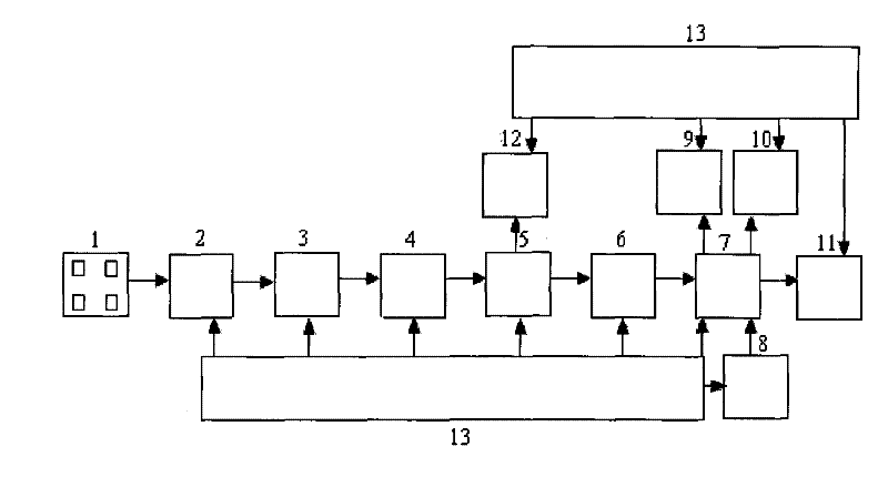
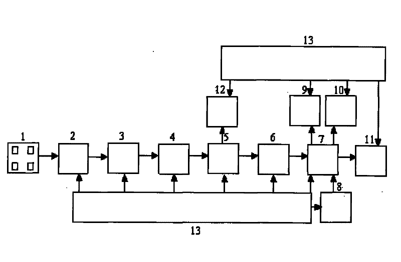
[0016] like figure 1 In the detection device shown, the output of the array piezoelectric crystal sensor 1 is connected to the charge amplifier 2, and the output of the charge amplifier 2 is sequentially connected in series with the gain adjustable circuit 3, the high-pass filter circuit 4, the sensitivity adjustment circuit 5, the pulse shaping circuit 6, the single On-chip microprocessor 7 and communication interface circuit 11. Wherein, the output of the sensitivity adjustment circuit 5 is bypassed to the sensitivity voltage display digital tube 12 , and the output of the single-chip microprocessor 7 is also connected to the alarm circuit 9 and the main display digital tube 10 . The output of the keyboard 8 is connected to the single-chip microprocessor 7 . Power supply circuit 13 connects above-mentioned each circuit respectively and provides power supply for each circuit, and power supply circuit 13 also connects charge amplifier 2, single-chip microprocessor 7, keyboard...


PUM

PropertyMeasurementUnit
Thicknessaaaaaaaaaa

Abstract

The invention discloses a grain cleaning loss detection method for a combined harvester and a device thereof. An array type piezoeletric quartz sensor is installed at the outlet of a cleaning sieve, the signal output from the array type piezoeletric quartz sensor is transmitted into a charge amplifier and a gain adjustable circuit to be processed and converted into a voltage signal with a certain amplitude value; a high pass filtering circuit and a sensitivity regulating circuit are used to respectively separate out the features of the vibration noise and the grain signals from the frequency domain and the time domain; the separated vibration noise and grain signals are rectified into standard pulse signals which can be executed by a micro monolithic processor through a pulse shaping circuit; the grain cleaning loss is detected by the method of full-width distribution of multi-lamella piezoelectric detection array, information is acquired from multiple areas and multiple angles, thereby enhancing the grain impact signals, improving the grain-grass identification precision and improving the testing reliability of the system; the detecting device has the advantages of good integral dynamic performance, strong anti-jamming capability, and high measurement precision, thereby realizing online measurement of the cleaning loss in the field.

Description

technical field [0001] The invention relates to a combine harvester among agricultural machinery, in particular to a performance test of the combine harvester, which is used for intelligent detection of grain cleaning loss. Background technique [0002] In the performance test of the combine harvester, the grain cleaning loss rate is an important index, which directly affects the production efficiency and operation quality of the harvester. In grain harvesting operations, when the moisture content of the stalks is low, a large number of broken stalks produced during the threshing process will increase the cleaning load, reduce the cleaning quality, and the cleaning loss rate is as high as about 4%, which greatly reduces the operating cost. quality. For a long time, the detection of this index has been using manual counting and manual calculation of the loss rate. The disadvantages are: low work efficiency, large errors, and inability to guide the harvesting operation of the...

Claims


Application Information

Patent Timeline
IPC IPC(8): A01D41/127G01N15/02
Inventor 毛罕平倪军李萍萍左志宇张晓东
Owner JIANGSU UNIV
Why Eureka
Try Eureka