
Microcomputer controlled and storage battery driven high-rise building fire high-speed escape elevator

A technology of microcomputer control and high-rise buildings, which is applied to elevators in buildings, sustainable buildings, and energy efficiency of elevators. problems, to achieve the effect of realizing network management, improving rescue efficiency and safety, and powerful functions

Inactive Publication Date: 2010-06-23
唐海山
View PDF4 Cites 19 Cited by
  • Summary
  • Abstract
  • Description
  • Claims
  • Application Information

AI Technical Summary

Problems solved by technology

The basic principle of various descending devices is a centrifugal speed limiter, most of which have no speed control device, and cannot slow down when encountering obstacles on the way down or reaching the ground, which will easily affect the safety of use
The operating speed of the life-saving slow-descent device is generally very low, about 1 m / s or less, and a small amount can reach 1.5 m / s. Therefore, it cannot be used in high-rise buildings.
A small number of high-speed descent devices are equipped with manual control devices, but the passengers need to have high control ability. In addition, the riding devices are simple, and most of them land by the window sills, causing the passengers to have a sense of fear. It is not suitable for escape. More than half of them are old. Use by weak, sick, disabled, women and children
Therefore, this type of life-saving and escape equipment is mainly suitable for low-floor, slow-moving, and physically strong groups, and it is difficult to undertake the task of fast, efficient and safe escape for the whole group of people.
[0009] As mentioned above, so far, there is still no efficient, reliable and safe escape equipment for high-rise building fires, making the escape of high-rise building fires a worldwide problem

Method used


Image

  • Microcomputer controlled and storage battery driven high-rise building fire high-speed escape elevator
  • Microcomputer controlled and storage battery driven high-rise building fire high-speed escape elevator
  • Microcomputer controlled and storage battery driven high-rise building fire high-speed escape elevator

Examples


Embodiment Construction

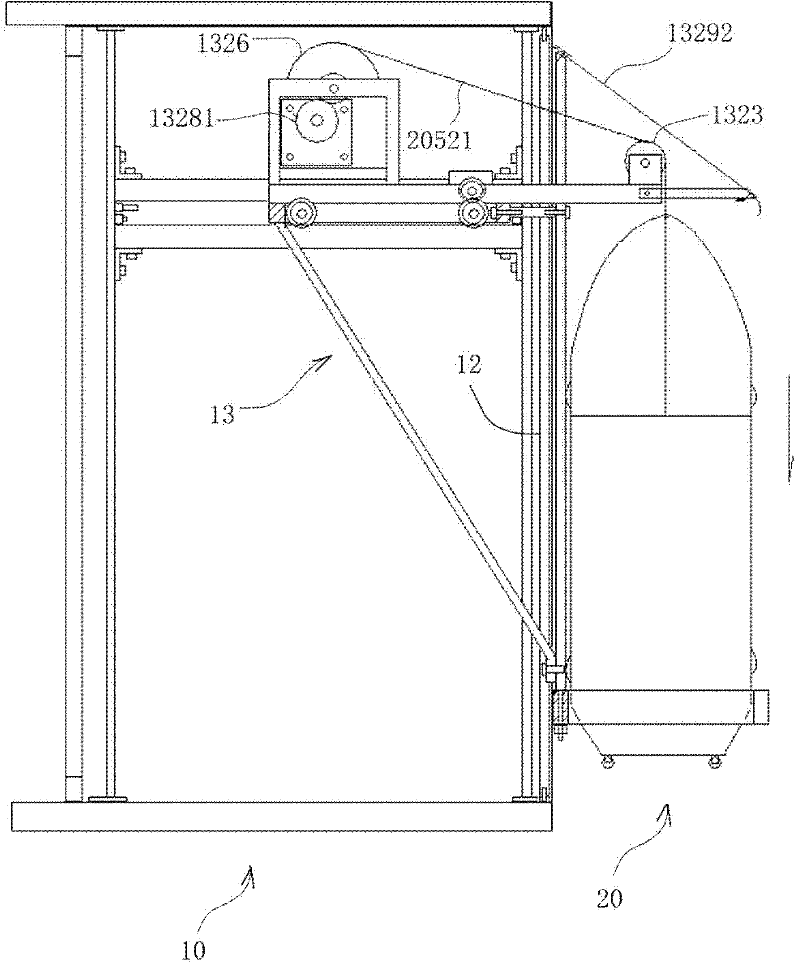
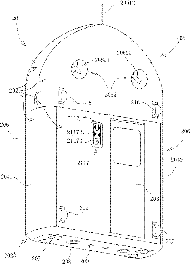
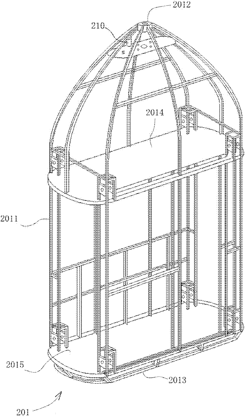
[0041] refer to figure 1 , the microcomputer-controlled and battery-driven high-speed fire escape elevator for high-rise buildings of the present invention includes a refuge and escape elevator room 10, a high-speed escape elevator host 20 and a control device 30.

[0042] The structure of the escape elevator room is as follows: Figure 3A As shown, the refuge and escape elevator room 10 is arranged in each unit or each household on each floor of a high-rise building. On the side of the outer wall of the household, the wall is constructed of the same material as the building wall. The escape elevator room 10 is provided with an entry door 11 and an escape door 12, wherein the entry door is arranged at a position where escape is the easiest. The entry door is made of fire-resistant and flame-retardant panels, such as fire-resistant and flame-retardant PC (polycarbonate) boards, and its edges are sealed with fire-resistant and flame-retardant foam sealing strips. The escape d...


PUM


Abstract

The invention relates to a microcomputer controlled and storage battery driven high-rise building fire high-speed escape elevator which comprises an evacuation escape elevator hall arranged in each unit or each house on each floor of a high-rise building, a high-speed escape elevator host configured in each evacuation escape elevator hall with the power supplied by a storage battery, a controller respectively arranged in the evacuation escape elevator hall and the high-speed escape elevator host with the power supplied by the storage battery; and in case of fire, the controller is operated, the high-speed escape elevator host carrying escapers is moved out of the high-rise building wall from the evacuation escape elevator hall, and is lowered onto the ground at high speed. The microcomputer controlled and storage battery driven high-rise building fire high-speed escape elevator has the advantages of safety, quickness, no restriction by the floor height and easy operation, and is convenient for the crew in the high-rise building to quickly escape immediately.

Description

【Technical field】 [0001] The invention relates to a fire escape device, in particular to a high-speed fire escape elevator for high-rise buildings controlled by a microcomputer and driven by a storage battery, which is used for escaping in case of fire for residents in family rooms, offices and hotel rooms in high-rise buildings. 【Background technique】 [0002] Since entering the 21st century, the process of industrialization and urbanization in various countries in the world has been further accelerated, resulting in a large increase in the number of high-rise buildings in cities. Crowds are densely packed in high-rise buildings, and a variety of electrical equipment, chemical fuels and chemical materials are used in large quantities, which leads to frequent fires in high-rise buildings and makes fire fighting, lifesaving and escape increasingly difficult. The continuous occurrence of fire accidents has become a worldwide problem that endangers public safety. [0003] Comp...

Claims


Application Information

Patent Timeline
IPC IPC(8): B66B9/00B66B11/04B66B1/24
CPCY02B50/142Y02B50/00
Inventor 唐海山
Owner 唐海山
Learn More