Lubricating method and lubricating structure of four-stroke gasoline engine

A lubrication structure, gasoline engine technology, applied in closed-circuit lubrication systems, mechanical equipment, engine components, etc., can solve the problems of high cost, many steps, low reliability, etc., and achieve the effect of fewer parts, simple steps, and remarkable effect.

Inactive Publication Date: 2010-06-23
昆山兴宝塑料制品有限公司
View PDF0 Cites 8 Cited by
  • Summary
  • Abstract
  • Description
  • Claims
  • Application Information

AI Technical Summary

Problems solved by technology

However, the problems existing in the existing small general-purpose gasoline engines are: the lubrication problem in the range of 360° cannot be effectively solved, and the oil enters the combustion chamber when it is inverted, resulting in flameout, and it is difficult to start repeatedly
[0005] The generation of oil mist in the lubricating system disclosed in the Japanese patent is formed by stirring the lubricating oil through the oil thrower 2, and then the oil mist enters the crankcase chamber 6 through the oil supply passage 3 for lubrication, and the lubricating oil atomization and the oil mist are separated. The lubricating action is completed in two devices through two steps; the oil mist generation process of the lubricating system disclosed in the Chinese patent is to drive the lubricating oil throug

Method used


Image

  • Lubricating method and lubricating structure of four-stroke gasoline engine
  • Lubricating method and lubricating structure of four-stroke gasoline engine
  • Lubricating method and lubricating structure of four-stroke gasoline engine

Examples


Embodiment Construction

[0033] In order to be able to understand the technical means of the present invention more clearly, it can be implemented according to the contents of the description, and in order to make the above content and other purposes, features and advantages of the present invention more obvious and understandable, a preferred embodiment is specifically cited, and With accompanying drawings, the detailed description is as follows.

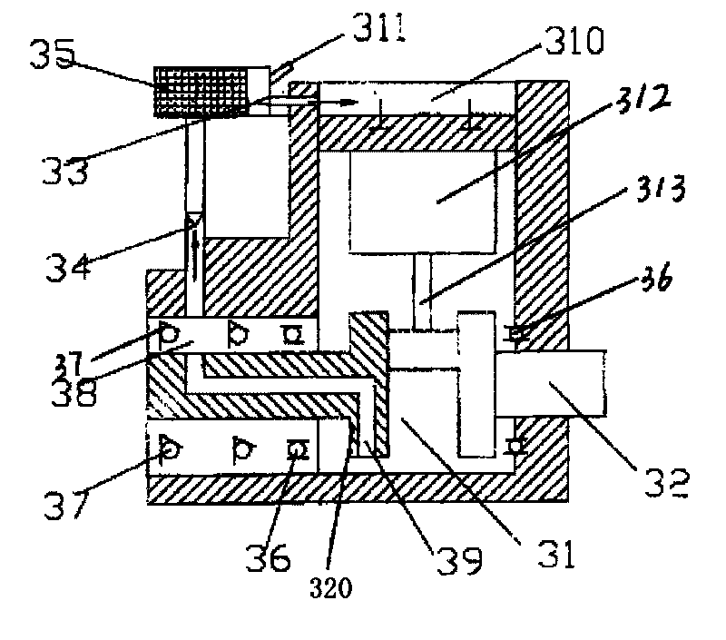
[0034] like image 3As shown, the lubricating method of the four-stroke gasoline engine of the present invention mainly includes two steps of crushing of lubricating oil, atomization and lubricating action of oil mist. The pressure causes the lubricating oil in the crankcase chamber 31 to splash, and the splashed lubricating oil is broken under the motion of the crankshaft 32 and its mechanism; when the piston 312 descends again, the pressure generated prompts the broken lubricating oil to atomize rapidly , when the pressure in the crankcase chamber 31 ri...


PUM


Abstract

The invention discloses a lubricating method and a lubricating structure of a four-stroke gasoline engine. Pressure generated by downward movement of a piston inside a crankcase coordinates with a crankshaft and structural movement of the crankshaft to atomize lubricating oil, pressure difference between the crankcase, a gas-oil separating chamber and a valve chamber is employed to make oil mist enter the lubricating travel in order to lubricate associated parts, and an inlet one-way valve and an outlet one-way valve are used for separating oil and gas and returning the lubricating oil. The atomization of the lubricating oil and the lubricating movement of the oil mist are implemented in the same device through two steps of beating and atomization of the lubricating oil and the lubricating movement of the oil mist, which is characterized by simple steps, less parts, low cost and high reliability. A vent hole of the crankshaft is used for ensuring that the lubricating oil can never enter the gas-oil separating chamber whether a motor works or not, and the lubricating structure can continuously and effectively work for more than two hours during 360 degrees turning without flameout and smoking.

Description

technical field [0001] The invention relates to a lubricating method and structure of a gasoline engine, in particular to a lubricating method and structure of a four-stroke gasoline engine. Background technique [0002] At present, the application fields of small general-purpose gasoline engines are becoming more and more extensive at home and abroad. In many occasions, such as: chain saws, shearing machines, military generators, etc., the engine is required to work effectively and normally in any direction within the range of 360°. But the problem that existing small general-purpose gasoline engine exists is: can't effectively solve the lubrication problem in 360 ° range, and when inverting, oil enters combustion chamber and causes flameout, and repeated starting is difficult. [0003] There are two typical lubricating systems for small general-purpose gasoline engines that can work normally within the range of 360°: one is the lubricating system disclosed by the Japanese ...

Claims


Application Information

Patent Timeline
IPC IPC(8): F01M1/12F01M13/04
Inventor 王俊哲李红枫吴定昌
Owner 昆山兴宝塑料制品有限公司
Why Eureka
Try Eureka