Cyclone type oil-gas separator of engine

An oil and gas separator, cyclone technology, applied in the direction of engine components, machines/engines, mechanical equipment, etc., can solve problems affecting engine performance, valve carbon deposition, etc., to improve the effect of hitting the wall, reduce emissions, and reduce oil consumption. Effect

Inactive Publication Date: 2010-06-23
CHONGQING CHANGAN AUTOMOBILE CO LTD
View PDF0 Cites 20 Cited by
  • Summary
  • Abstract
  • Description
  • Claims
  • Application Information

AI Technical Summary

Problems solved by technology

Therefore, a large amount of oil and gas will still enter the intake system, causin

Method used


Image

  • Cyclone type oil-gas separator of engine
  • Cyclone type oil-gas separator of engine
  • Cyclone type oil-gas separator of engine

Examples


Embodiment Construction

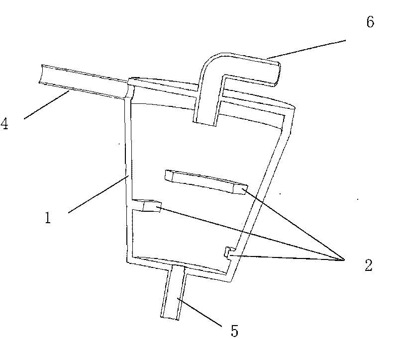
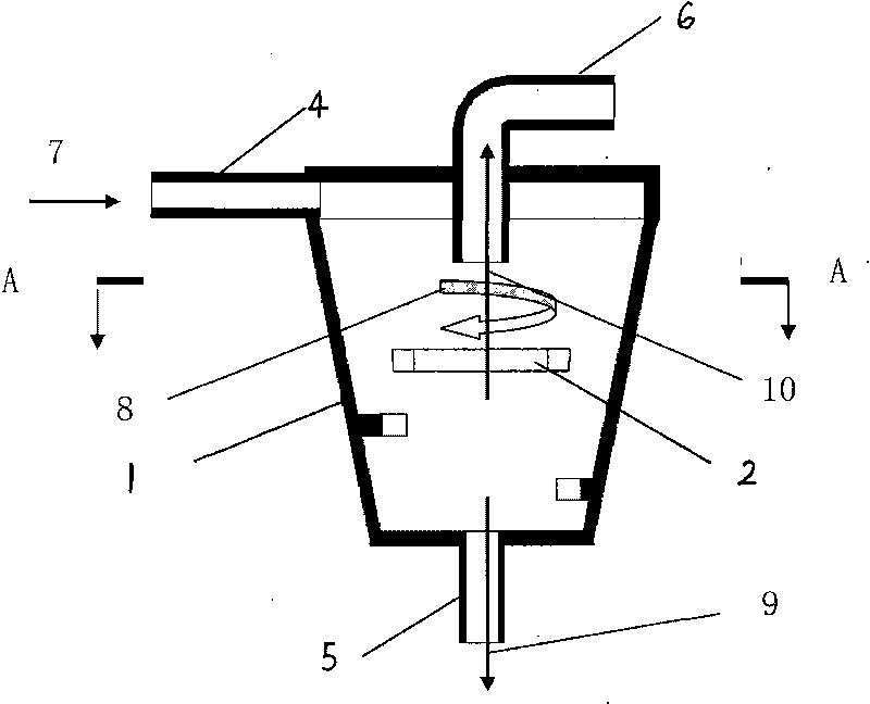
[0013] The structure of the present invention is described in detail below in conjunction with accompanying drawing:

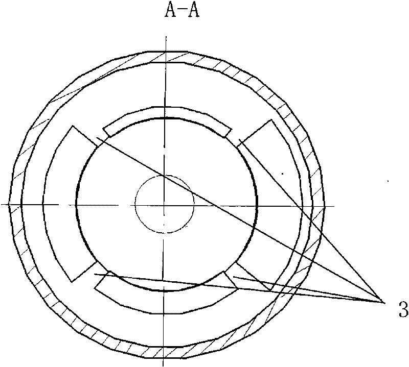
[0014] see figure 1 and figure 2 , the cyclone type oil-gas separator includes a conical cavity 1, the same as the existing similar oil-gas separator, the upper side wall of the conical cavity 1 is provided with a mixed oil-gas inlet pipe 4, the top has an exhaust port 6, and the bottom has Oil return port 5, they are all combined together by plastic molding process, and the whole cyclone oil-air separator is connected to the engine cylinder head by bolts. The difference is that the inner wall of the conical cavity 1 is not smooth, and a spiral labyrinth separation channel 2 is arranged on the inner wall of the conical cavity 1 from top to bottom, forming a spiral labyrinth structure. The spiral labyrinth separation channel 2 is a convex line formed on the inner wall surface of the conical cavity 1, spirally descends on the inner wall of the conical cavity...


PUM


Abstract

The invention provides a cyclone type oil-gas separator of an engine. The separator comprises a conical cavity body, wherein the side wall of the upper part of the conical cavity body is provided with a mixed oil-gas inlet tube, the top part of the conical cavity body is provided with a gas discharge opening, and the bottom part of the conical cavity body is provided with an oil return opening; and the inner wall of the conical cavity body is provided with a spiral type maze separation path from the top to the bottom, the spiral type maze separation path is a protruding strip forming the surface of the inner wall of the conical cavity body and spirally goes down on the inner wall of the conical cavity body, and the spiral type maze separation path is of a discontinuous type. The separator adopts a structure of the combination of the conical cavity body and the spiral type maze, so that under the same manufacturing process conditions, the separator has the advantages of improving the wall collision effect when the oil and the gas centrifugally rotate, improving the adhesive capability of the oil and the gas, reducing the amount of the mixed gas entering a combustion chamber of the engine, lowering emission, and reducing the consumption of engine oil.

Description

technical field [0001] The invention relates to the technical field of crankcase ventilation of an automobile engine, in particular to a cyclone type oil-gas separator. Background technique [0002] During the compression stroke of the gasoline engine, a small amount of mixed gas in the cylinder leaks into the crankcase through the gap between the piston ring and the cylinder hole, the gap between the piston ring cutout, the gap between the valve and the valve guide, etc., most of which is unburned gasoline, and the emission is hydrocarbon compound. According to national regulations, the mixed gas cannot be discharged into the atmosphere, but if it is not disposed of, it will easily cause the oil to precipitate and affect the lubricating performance of the oil. The accumulation of a large amount of mixed gas will also cause the pressure inside the crankcase to rise, causing oil seal Wait for the sealing structure to leak. The ventilation system is to introduce an appropria...

Claims


Application Information

Patent Timeline
IPC IPC(8): F01M13/04
Inventor 梁文锋赵勇何海波罗凯
Owner CHONGQING CHANGAN AUTOMOBILE CO LTD
Why Eureka
Try Eureka