Supercharge Your Innovation With Domain-Expert AI Agents!

Light emitting diode (LED) backlight structure

A technology of backlight structure and light source, applied in the directions of optics, light guide, light source, etc., can solve the problems of insufficient partition, uneven image boundary, pixel correspondence, etc., and achieve the effect of eliminating unevenness.

Inactive Publication Date: 2010-06-23
AU OPTRONICS CORP
View PDF0 Cites 6 Cited by
  • Summary
  • Abstract
  • Description
  • Claims
  • Application Information

AI Technical Summary

Problems solved by technology

[0003] For backlight displays, the LED backlight panels in the prior art cannot completely correspond to the pixels in the pixel plane because the partitions are not detailed enough, so the boundary of the image is often uneven.

Method used


Image

  • Light emitting diode (LED) backlight structure
  • Light emitting diode (LED) backlight structure
  • Light emitting diode (LED) backlight structure

Examples


Embodiment Construction

[0016] Specific embodiments of the present invention will be described in detail below with reference to the accompanying drawings.

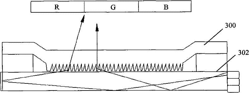
[0017] Before describing the specific implementation of the present invention, the TMOS technology is briefly introduced. The full name of TMOS technology is time-sequential multiplexing optical shutter technology, in which time-sequential multiplexing is an image formation method of a display. For a full-color image, red light, green light and blue light are injected sequentially, and the MEMS switch determines which color light will be transmitted at what time. In this sense, sequential multiplexing in TMOS technology is also the field sequential color generation process. It is not difficult to see that this method of sequential multiplexing is fully compatible with the construction basis in the existing technology, and does not require the manufacturer to rebuild the production workshop. In addition, it also gets rid of the filters required...


PUM


Abstract

The invention provides an LED backlight structure based on the time multiplexed optical shutter (TMOS) technology, at least comprising a light source, a light guide plate and an OpcuityTM active layer. The light guide plate is provided with a thin film transistor (TFT) array and is used for receiving light from the light source. The OpcuityTM active layer is arranged opposite to the light guide plate and comprises a substrate thin film, a flexible lead arranged above the substrate thin film and a micro-electromechanical system (MEMS) element arranged above the flexible lead, wherein the MEMS element of the active layer is arranged corresponding to a liquid crystal display (LCD) pixel. In the LED backlight structure, because the MEMS element (for example, a micro-optical layer) completely corresponds to the pixel on an LCD pixel plane, global dimming and local dimming can be simultaneously realized by adopting the working principle of destroying total reflection, and the nonuniform phenomenon caused by the image boundary can be eliminated.

Description

technical field [0001] The present invention relates to an LED backlight structure, in particular to an LED backlight structure based on TMOS (Time Multiplexed Optical Shutter, time sequence multiplexed optical shutter). Background technique [0002] Currently, liquid crystal displays (LCDs, Liquid Crystal Displays) are increasingly widely used along with the continuous advancement of their own technology. Products in many fields such as telecommunications, Internet equipment, test / measurement instruments, handheld data management equipment, control panel automatic displays, office equipment, notebook computers, and video game consoles are the stage where LCDs can show their talents. According to the type of light emission, LCD backlight mainly includes three types: electroluminescence (EL), cold cathode fluorescent lamp (CCFL) and light-emitting diode (LED). Faster start-up time and wider color gamut, no need for current converters, and no mercury components, making it wid...

Claims


Application Information

Patent Timeline
IPC IPC(8): F21S8/00F21V8/00F21V13/00F21V23/00G02F1/13357F21Y101/02
Inventor 陈志光
Owner AU OPTRONICS CORP
Features
  • R&D
  • Intellectual Property
  • Life Sciences
  • Materials
  • Tech Scout
  • Unparalleled Data Quality
  • Higher Quality Content
  • 60% Fewer Hallucinations
Learn More