Waste heat exchange device for textile setting machine

A technology of heat exchange device and setting machine, which is applied in the processing of textile material equipment configuration, indirect heat exchanger, lighting and heating equipment, etc., which can solve the problems of inconsistent quality and performance, inconvenient maintenance, low heat transfer efficiency, etc., and achieve improvement Heat exchange effect and service life, effect of high thermal conductivity

Inactive Publication Date: 2011-04-06
李天德
View PDF5 Cites 1 Cited by
  • Summary
  • Abstract
  • Description
  • Claims
  • Application Information

AI Technical Summary

Problems solved by technology

[0006] The purpose of the present invention is to provide a waste heat heat exchange device for a textile setting machine, which can overcome the defects of single-pipe arrangement of finned heat pipes in the prior art, inconsistent quality and performance, inconvenient maintenance, and low heat transfer efficiency; The liquid phase and gas phase in the sheet heat pipe are transformed into each other to improve the heat transfer and heat dissipation effect

Method used


Image

  • Waste heat exchange device for textile setting machine
  • Waste heat exchange device for textile setting machine
  • Waste heat exchange device for textile setting machine

Examples


Embodiment Construction

[0045] The structure of the present invention will be further described in detail below in conjunction with the accompanying drawings.

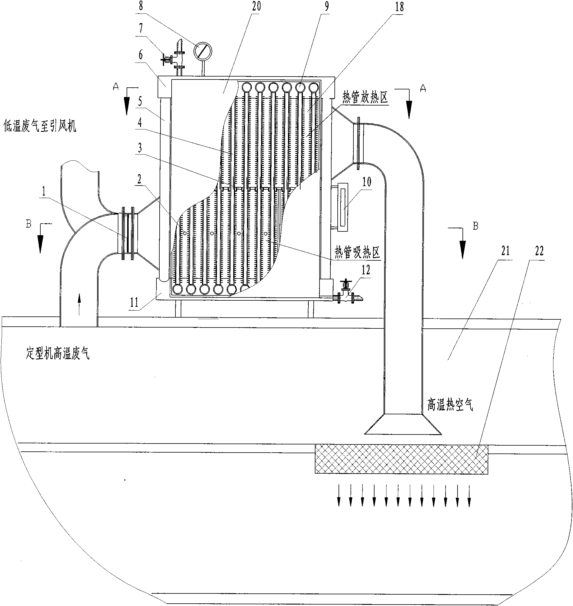
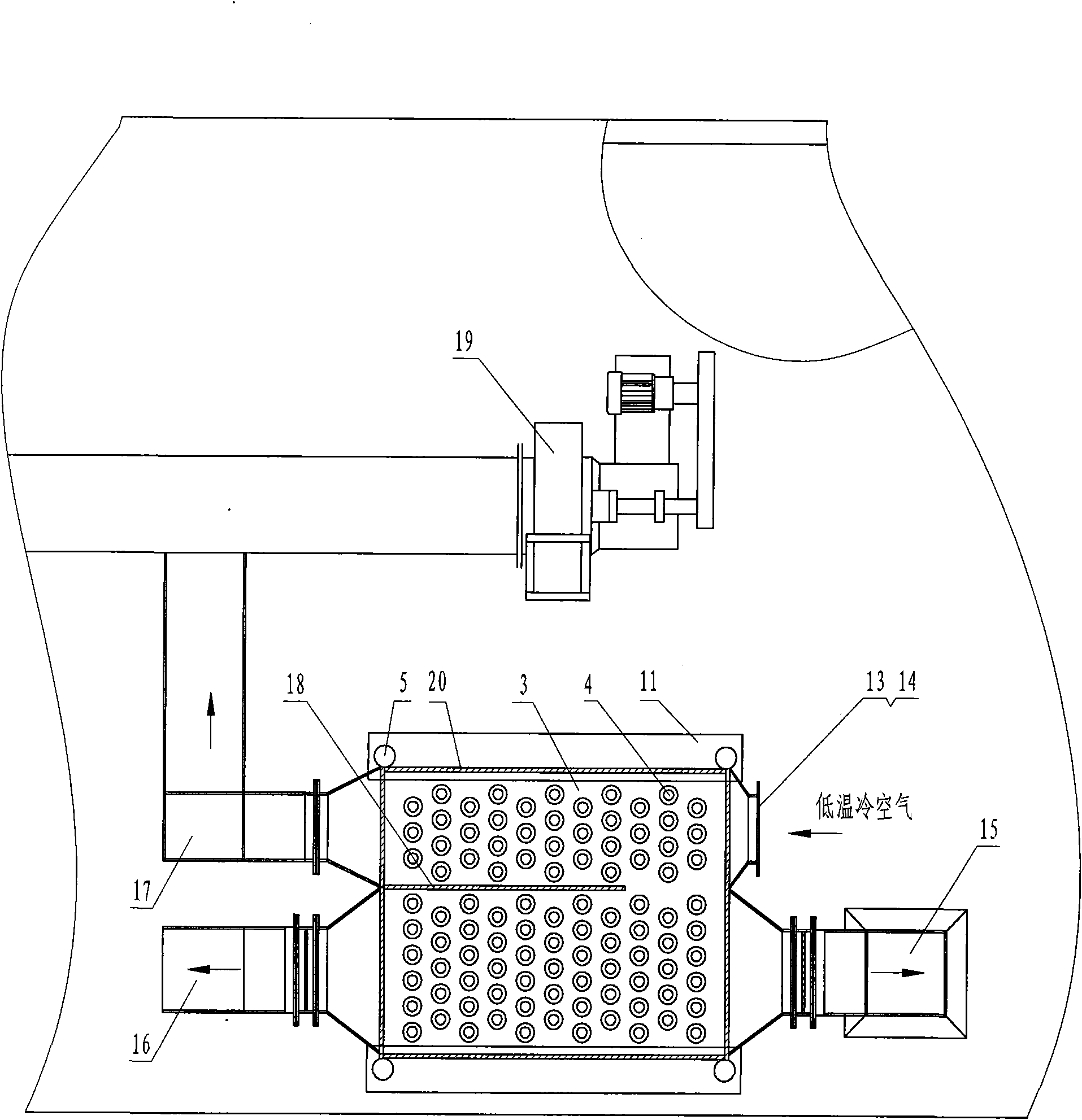
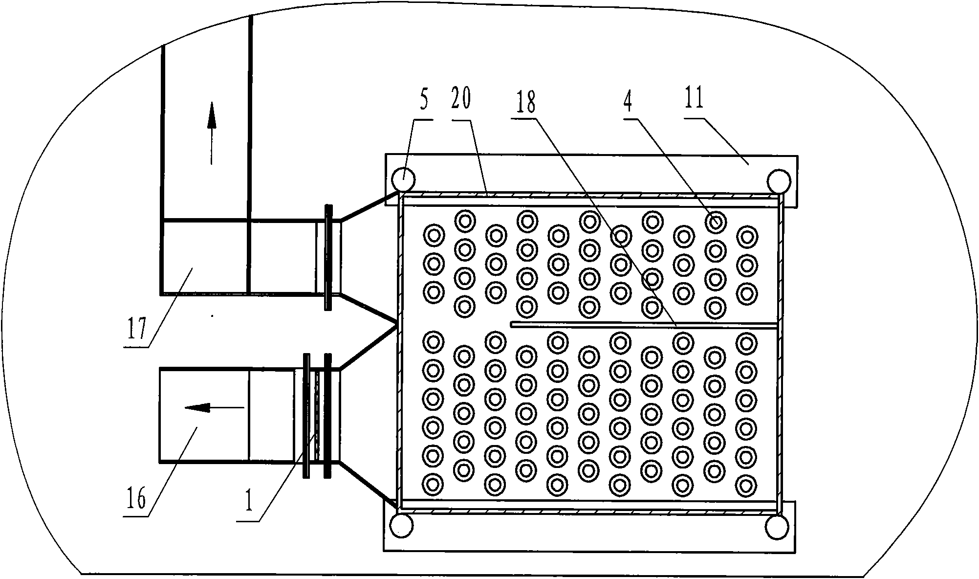
[0046] A waste heat heat exchange device for a textile setting machine, comprising finned heat pipes 4, a plurality of finned heat pipes 4 are vertically arranged, and the upper and lower ends are connected to header connecting pipes 9 arranged horizontally to form a rectangular heat transfer row;

[0047] Multiple rows of heat transfer rows are arranged in parallel, and the left and right sides of the upper and lower parts are respectively connected by two vertically arranged upper headers 6 and lower headers 11 to connect the header connecting pipes 9 of each row to form a rectangular heat transfer body. The outer side of the heat transfer body is a closed casing 20;

[0048] The rectangular heat transfer body is separated by the middle tube plate 3 to form an upper half heat transfer body and a lower half heat transfer body, the upper half...


PUM


Abstract

The invention relates to a main working auxiliary machine for a textile machinery setting machine, and discloses a waste heat exchange device for a textile setting machine. The device comprises a plurality of fin heat pipes (4) which are vertically arranged, and the upper and lower ends of the fin heat pipes are communicated with container connecting pipelines (9) to form heat transfer rows; and a plurality of heat transfer rows are arranged in parallel, an upper container (6) and a lower container (11) are communicated and connected to form a rectangular heat transfer body, and a middle pipeplate (3) divides the rectangular heat transfer body into an upper half heat transfer body and a lower half heat transfer body. Upper and lower guide plates (18) vertically divide a heat absorption layer and a heat release layer respectively, and an air inlet, an air inlet passage, a turning passage, an air outlet passage and an air outlet are formed on each layer surface respectively; and a working substance down pipe (5), a liquid filling port (7) and a working substance discharge port (12) are arranged between the upper and lower containers. The invention provides the scheme of vertically arranging the fin heat pipes (10) for the first time, so the heat absorption and heat release of the device are more sufficient and the effect is better; the device is more favorable for phase state conversion for the medium in the fin heat pipes; and the heat exchange device for the setting machine is convenient to maintain, and the medium is convenient to change.

Description

technical field [0001] The invention is an auxiliary device of a textile machinery setting machine, in particular relates to a heat exchange device for supplementing air by using the waste heat of the textile setting machine. Background technique [0002] The setting machine (or tentering machine) is one of the main production and processing machines in the textile industry, and it is widely used. The sizing machine is a device for finishing the fabric after textile printing and dyeing. The sizing machine needs high temperature heating. The heating method can be directly burning gas or light diesel oil in the sizing machine, or can be heated by circulating hot oil or steam, or electric heating. Generally, the temperature of the hot air required in the heat-setting oven is about 200°C. The cloth is dried in the high-temperature environment of the setting machine while being conveyed in a tight state. The length of the setting machine is more than 30 meters, and the width is u...

Claims


Application Information

Patent Timeline
Patent Type & Authority Patents(China)
IPC IPC(8): D06B23/20F28D15/02
Inventor 李天德
Owner 李天德
Why Eureka
Try Eureka