
Bonding device of direction-finder

An orientation instrument and bonding technology, applied in the direction of fine working devices, electrical components, working accessories, etc., can solve the problems of out-of-tolerance finished products and inability to adjust the deviation angle, and achieve the effect of small investment and simple use

Inactive Publication Date: 2010-06-30
DONGDAN AOLONG RADIATIVE INSTR GRP
View PDF0 Cites 11 Cited by
  • Summary
  • Abstract
  • Description
  • Claims
  • Application Information

AI Technical Summary

Problems solved by technology

However, the adjustment on the processing machine tool can only be adjusted on one plane. If the adjustment needs to be carried out on a plane perpendicular to the adjustable plane, you need to give up this bonding and re-bond the material.
Another bonding method is to place the material plate on the orientation instrument, and then bond it to the cutting material plate on the orientation instrument after detection. The disadvantage of this method is that it can only correct the deviation angle in the plane of the material plate, and the material plate The deviation angle in the vertical plane can never be adjusted
When high-precision slicing is required, only this deviation can cause the finished product to be out of tolerance, and sometimes it is necessary to re-glue the material

Method used


Image

  • Bonding device of direction-finder
  • Bonding device of direction-finder
  • Bonding device of direction-finder

Examples


Embodiment Construction

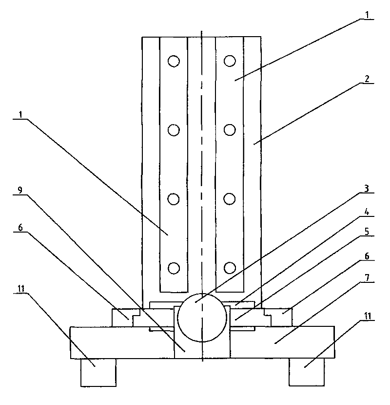
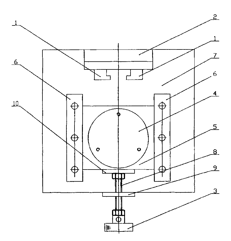
[0009] The present invention will be further described below in conjunction with the accompanying drawings.

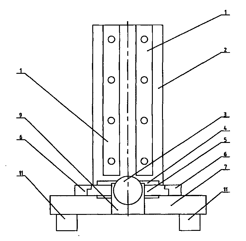
[0010] A bonding device for an orientation instrument, such as figure 1 , figure 2 As shown, it is characterized in that: four legs 11 are arranged below the base 7, a graphite block guide rail 6 is installed on the base 7, a T-shaped block 5 is inserted in the graphite guide rail 6, and the T-shaped block 5 can move relative to the graphite block guide rail 6 , a graphite block 4 is installed on the top of the T-shaped block 5, a flange 10 is installed on the middle position of the front of the T-shaped block 5, and one end of the screw 8 arranged at the middle position of the front of the T-shaped block 5 is connected to the hand button 3, and the other end is screwed into the The nut plate 9 arranged on the base 7 is connected to the flange 10 . The present invention is an auxiliary device specially designed for the X-ray orientation instrument for measuring the ...


PUM


Abstract

The invention relates to a bonding device used for an X-ray direction-finder which is used to measure the crystal orientation deviation of crystal or the crystal orientation position of processed crystal face of crystal bar. The structure of the bonding device is as follows: four supporting feet are arranged under a base, a graphite block slideway is arranged on the base, a T-shaped block is inserted in the graphite block slideway, a graphite block is arranged on the T-shaped block, a binding slideway is arranged on a vertical plate which is fixed on the upper part of the back of the base, a flange is arranged in the mid-position of the front of the T-shaped block, one end of a screw arranged in the mid-position of the front of the T-shaped block is connected with a hand knob, and the other end is screwed in a nut board arranged in the mid-position of the front of the base to be connected with the flange. The device can be used to ensure that the crystal face and the end surface of the graphite block are perpendicular to the axis of crystal rod, the deviation angle in a retainer plate plane can be adjusted, the deviation angle in a plane which is perpendicular to the retainer plate can be adjusted, the bonding device can satisfy the binding demand of crystal rod with different diameters and the high precision slicing demand, the investment is less, the operation is easy, convenient and reliable, and the aim of binding various crystal rods can be effectively achieved.

Description

technical field [0001] The invention relates to an X-ray detection instrument tooling device, in particular to a bonding device used for an X-ray orientation instrument used for measuring the crystal orientation deviation or the crystal orientation position of the crystal plane to be processed. Background technique [0002] All kinds of artificial lenses are used by cutting into thin slices. As we all know, their hardness is high, resulting in time-consuming and labor-intensive processing, and relatively speaking, the price of raw materials is also high. Therefore, it is necessary to measure the crystal orientation deviation or the crystal orientation position of the crystal ingot to be processed before processing in order to achieve accurate orientation and reduce waste of raw materials. At present, processing manufacturers basically use orientation instruments to measure and determine after measurement. Cut after the cut position. Before cutting, the crystal or ingot need...

Claims


Application Information

Patent Timeline
Patent Type & Authority Applications(China)
IPC IPC(8): B28D7/04B28D5/00H01L21/304
Inventor 隋凤丽许秋华宋伟李国兴
Owner DONGDAN AOLONG RADIATIVE INSTR GRP
Learn More