Manufacturing method of reinforcement cage of pouring pile with large diameter

A manufacturing method and reinforcement cage technology, which is applied in sheet pile walls, buildings, and foundation structure engineering, etc., can solve the problems of poor positioning accuracy of main reinforcement and reinforcement stirrups, low manufacturing quality, and slow progress of the project, and achieve high-quality cage manufacturing. Ergonomics, high manufacturing precision, and reduced labor intensity

Active Publication Date: 2010-06-30
SHANGHAI GUANGLIAN ENVIRONMENTAL & GEOTECHNICAL ENG CO LTD
View PDF0 Cites 20 Cited by
  • Summary
  • Abstract
  • Description
  • Claims
  • Application Information

AI Technical Summary

Problems solved by technology

[0003] Traditional cast-in-place pile reinforcement cages are all made manually. Since the main reinforcement of a single-section reinforcement cage for large-diameter cast-in-place piles has dozens of main reinforcements (for example, for a load-bearing cast-in-place pile with a diameter of Φ4200, the diameter of the reinforcement cage is usually 4m. This reinforcement cage The design quantity of the main reinforcement is generally 60-90), so a large amount of labor is required to carry the steel bars during production, which has the defects of high labor intensity, slow progress of the project, and low production efficiency. The spacing and positioning accuracy between the main reinforcement and the reinforcement stirrup are also poor, and the production quality is not high

Method used


Image

  • Manufacturing method of reinforcement cage of pouring pile with large diameter
  • Manufacturing method of reinforcement cage of pouring pile with large diameter
  • Manufacturing method of reinforcement cage of pouring pile with large diameter

Examples


Embodiment Construction

[0044] The embodiments of the present invention will be described in further detail below in conjunction with the accompanying drawings, but the present embodiments are not intended to limit the present invention, and any similar structures and similar changes of the present invention should be included in the protection scope of the present invention.

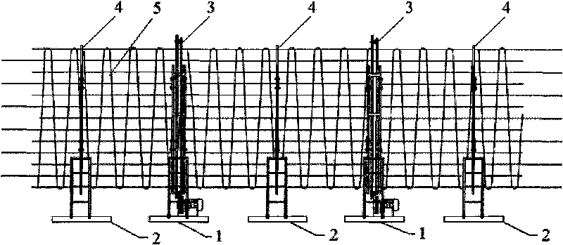
[0045] Such as figure 1 As shown, the manufacturing device of a large-diameter cast-in-place pile reinforcement cage provided by the embodiment of the present invention is characterized in that it includes a plurality of support frame assemblies; there are two types of support frame assemblies, one of which is a rolling support frame assembly 2, the other is the transmission support frame assembly 1; each rolling support frame assembly 2 and each transmission support frame assembly 1 are arranged alternately on the ground along the central axis of the reinforcement cage; the central axis of the reinforcement cage is a horizonta...


PUM


Abstract

The invention discloses a manufacturing method of a reinforcement cage of a pouring pile with the large diameter, relating to the technical field of construction project. The invention aims at reducing the labor intensity while improving manufacturing accuracy and work efficiency. The method is characterized in that a manufacturing device consisting of a plurality of rolling bearing frame assemblies and transmission bearing frame assemblies is arranged according to a projection line of a central axis line of the reinforcement cage; openable ring mould assemblies are arranged on each transmission bearing frame assembly; inner walls of the ring mould assemblies are provided with a plurality of main reinforcement positioning grooves; main reinforcements of the reinforcement cage is lifted into the ring mould assemblies, the ring mould assemblies are driven through a low-speed drive gear to rotate so that each main reinforcement enters the main reinforcement positioning grooves and is fixedly welded with rectilinear hoops; and the ring mould assemblies are rotated and winded and reinforcing steel bars are rounded by using spot welding so as to realize mechanization manufacture of the reinforcement cage of the pouring pile with the large diameter. The method provided by the invention can realize high manufacturing accuracy and cage-making work efficiency of the reinforcement cage, can greatly reduce the labor intensity and reduce the worker amount of unit cage manufacture amount and is beneficial to quickening the project progress.

Description

technical field [0001] The invention relates to construction engineering technology, in particular to a technology for manufacturing a large-diameter cast-in-situ pile reinforcement cage used for large-scale and super-large bridge pile foundations. Background technique [0002] With the vigorous development of large and super large bridge construction in China, the design diameter of bored piles for main and auxiliary piers of large and super large bridges has been developed from about 2m to 3m ~ 4m. The design diameter of reinforcement) and reinforcement stirrup material is also increased from Φ25~Φ32 to Φ40~Φ50 (Φ50 is the largest diameter specification of rebar produced in China at present), and the weight of a single 12.5m long steel bar is also increased from 48kg~79kg To 123kg ~ 193kg. [0003] Traditional cast-in-place pile reinforcement cages are all made manually. Since the main reinforcement of a single-section reinforcement cage for large-diameter cast-in-place p...

Claims


Application Information

Patent Timeline
Patent Type & Authority Applications(China)
IPC IPC(8): E02D5/34
Inventor 顾源兴凡后奇李金元方兆昌
Owner SHANGHAI GUANGLIAN ENVIRONMENTAL & GEOTECHNICAL ENG CO LTD
Why Eureka
Try Eureka