Image current detecting circuit

A detection circuit, mirror current technology, applied in the direction of measuring current/voltage, measuring device, measuring electrical variables, etc., can solve the problems of poor mirror accuracy, small error, fast following speed, etc., to achieve convenient operation, fast speed, high precision Effect

Inactive Publication Date: 2010-06-30
天津南大强芯半导体芯片设计有限公司
View PDF6 Cites 6 Cited by
  • Summary
  • Abstract
  • Description
  • Claims
  • Application Information

AI Technical Summary

Problems solved by technology

[0002] In the current detection system, it is generally realized by detecting the mirror output power tube current. In order to improve the mirror image accuracy, it is necessary to follow the drain terminal voltage of the power tube, which is typically followed by the PN junction voltage of NPN and PNP. , this method has fast following speed and small error, but limited by the process, the process with NPN and PNP must be used, and the base current of the triode will have a certain influence; the other is through the gate of the NMOS tube and the PMOS tube In this way, the threshold voltage of NMOS and PMOS is different, and the two vary greatly with temperature and process, so the accuracy of the mirror image obtained is very poor.

Method used


Image

  • Image current detecting circuit
  • Image current detecting circuit
  • Image current detecting circuit

Examples


Embodiment

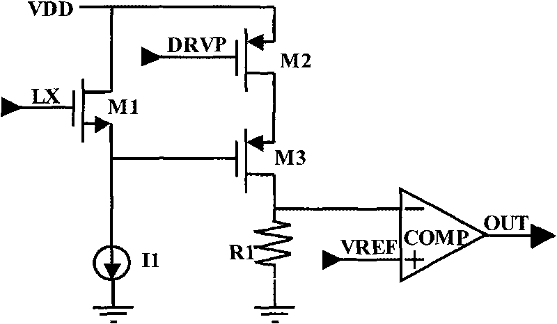
[0017] Embodiment: a kind of mirror current detection circuit (see figure 2 ), including the drive signal DRVP terminal of the output power tube, the drain voltage LX terminal of the output power tube, the power supply voltage VDD terminal, the reference voltage VREF terminal and the current detection output OUT terminal, it is characterized in that it is composed of a control switch unit, a current mirror unit , a voltage follower unit, a current-voltage conversion unit and a comparator unit; wherein, the input end of the control switch unit is respectively connected to the drive signal DRVP terminal of the output power tube, the drain terminal voltage LX terminal of the output power tube and the power supply voltage VDD terminal, its output terminal is connected to the input terminal of the current mirror unit and the input terminal of the voltage follower unit; the input terminal of the said current mirror unit is connected to the power supply voltage VDD terminal, and its ...


PUM


Abstract

The invention relates to an image current detecting circuit, which consists of a control switch unit, a current mirror unit, a voltage tracking unit, a current-voltage converting unit and a comparer unit. The image current detecting circuit has the advantages that: (1), a circuit of the current of an output power tube is detected by monitoring the current of a detecting tube which can reduce the output power tube by n times; (2), an image precision of the detecting tube is improved; (3), the speed of switching-off and power-on switching of the power tube is increased; (4), detection of the current has high precision and fast speed; and (5), the image current detecting circuit has simple circuit structure, convenient operation, and can be applied to the circuit in need of detecting the current of a large power tube.

Description

(1) Technical field: [0001] The invention relates to a current detection circuit, in particular to a mirror current detection circuit. (two) background technology: [0002] In the current detection system, it is generally realized by detecting the mirror output power tube current. In order to improve the mirror image accuracy, it is necessary to follow the drain terminal voltage of the power tube, which is typically followed by the PN junction voltage of NPN and PNP. , this method has fast following speed and small error, but limited by the process, the process with NPN and PNP must be used, and the base current of the triode will have a certain influence; the other is through the gate of the NMOS tube and the PMOS tube In this way, because the threshold voltages of NMOS and PMOS are different, and the two vary greatly with temperature and process, the image accuracy obtained is very poor. (3) Contents of the invention: [0003] The object of the present invention is to d...

Claims


Application Information

Patent Timeline
Patent Type & Authority Applications(China)
IPC IPC(8): G01R19/00
Inventor 吕英杰戴宇杰张小兴林鹏程
Owner 天津南大强芯半导体芯片设计有限公司
Why Eureka
Try Eureka