Optical pickup device and collimate lens

一种光拾取装置、准直透镜的技术,应用在光束引导装置、光束源、光学记录头等方向,能够解决位置调节难、交调失真、机构复杂等问题,达到吊架结构简化、占有容积降低、零件个数减少的效果

Inactive Publication Date: 2010-06-30
PANASONIC CORP
View PDF2 Cites 0 Cited by
  • Summary
  • Abstract
  • Description
  • Claims
  • Application Information

AI Technical Summary

Problems solved by technology

[0007] However, in a coma correction device using a liquid crystal element, there is a problem that only low-frequency angular deviation can be corrected, and it is difficult to reduce coma aberration generated in a wide range from low frequencies to high frequencies.
Therefore, the problem is that not only the mechanism is very complicated, but also there may be intermodulation distortion in the radial and tangential directions.
However, this situation is also the same as the case of the above-mentioned coma aberration correction transmission mechanism, and it is necessary to separately install the hangers in the radial direction and the tangential direction, which causes the problem that the resonance characteristics of the objective lens transmission mechanism are deteriorated, and the objective lens transmission mechanism is caused. upsizing
But, in this case, with regard to one objective lens, for example, the inclination of the objective lens can be adjusted and fixed when the objective lens actuator is installed on the optical pickup device; Tilt adjustment is performed without changing the positional relationship between the objective lens and the disc.
Moreover, these objective lenses are very small, and their position adjustment becomes a very difficult task
Therefore, a large-scale lens adjustment device and an adjustment work process are required.
[0017] In addition, in the above-mentioned BD, the information recording surface with a maximum of 2 layers is expected to increase in the future, and the distance between the information recording surface closest to the disc surface and the information recording surface farthest will be larger than it is now.

Method used


Image

  • Optical pickup device and collimate lens
  • Optical pickup device and collimate lens
  • Optical pickup device and collimate lens

Examples


Embodiment approach 1

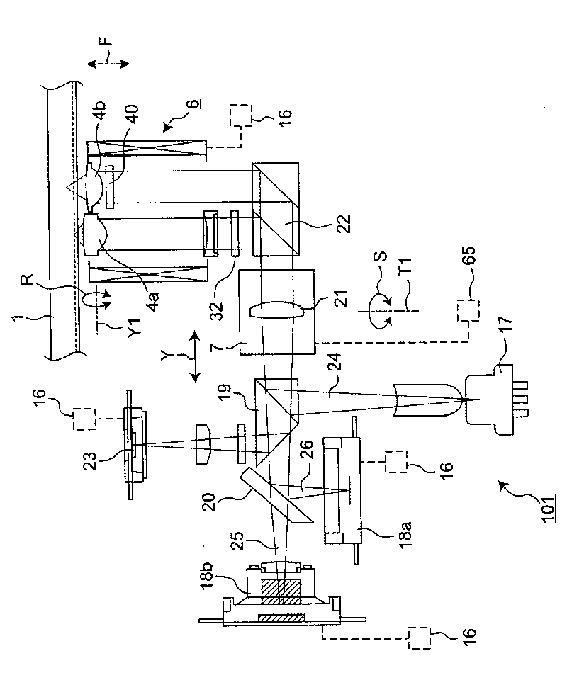
[0096] refer to figure 1 The configuration of the optical pickup device 101 according to Embodiment 1 of the present invention will be described.

[0097] The optical pickup device 101 of this embodiment is an optical pickup device that records or reproduces information by converging a light beam emitted from a light source toward an optical disc as an optical recording medium by a converging optical system on the optical recording medium. Such an optical pickup device 101 is roughly divided into the above-mentioned light source, a first coma correction actuator, and a second coma correction actuator. Here, the first and second coma aberration correction transmission mechanisms constitute a part of the above-mentioned condensing optical system. In addition, the first coma aberration correction actuator has a first tilt drive unit that tilts the objective lens that emits light onto the optical disc in a first inclination direction, and the second coma aberration correction act...

Embodiment approach 2

[0208] Next, an optical pickup device according to Embodiment 2 of the present invention will be described with reference to the drawings.

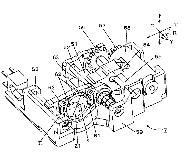
[0209] Figure 11 It is a configuration diagram showing the configuration of the collimator lens actuator 7-2 of the optical pickup device according to the second embodiment.

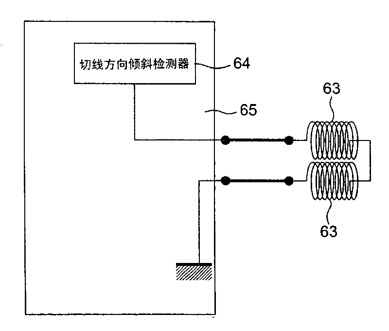
[0210] exist Figure 11 in, with figure 2 The difference of the collimator lens 7 shown is that the movable magnet 62 and the fixed tangential direction tilt coil 63 of the tangential direction tilt driving part of the collimator lens transmission mechanism 7, in the collimator lens transmission mechanism 7- 2 is replaced by a fixed magnet 66 and a movable tangentially inclined coil 67. In the collimator lens actuator 7 - 2 , the other components are not changed, and the same reference numerals are assigned to the components having the same functions as those of the collimator lens actuator 7 .

[0211] Therefore, hereby refer to Figure 11 With regard to the...

Embodiment approach 3

[0215] Next, an optical pickup device according to Embodiment 3 of the present invention will be described with reference to the drawings.

[0216] Figure 12 It is a configuration diagram showing the configuration of the collimator lens actuator 7-3 of the optical pickup device according to the third embodiment.

[0217] exist Figure 12 in, with figure 2 The difference of the collimator lens 7 shown is that the movable magnet 62 and the fixed tangential direction tilt coil 63 of the tangential direction tilt driving part of the collimator lens transmission mechanism 7, in the collimator lens transmission mechanism 7- 3, it is replaced by a piezoelectric element 68. In the collimator lens actuator 7 - 3 , the other components are not changed, and the same reference numerals are assigned to the components having the same functions as those of the collimator lens actuator 7 .

[0218] Therefore, hereby refer to Figure 12 Regarding the collimating lens transmission mechan...


PUM

PropertyMeasurementUnit
wavelengthaaaaaaaaaa

Abstract

It is possible to provide a small-size thin optical pickup device which can correct a coma aberration generated in a light collection optical system including an objective lens for an optical disc. The optical pickup device includes: a first coma aberration correction actuator (6) which has a first tilt drive unit for tilting the objective lens in a first tilt direction; and a second coma aberration correction actuator (7) which has a second tilt drive unit for tilting a coma aberration correction lens arranged between a light source and a start-up mirror for reflecting an outgoing light toward the objective lens, into a second tilt direction.

Description

technical field [0001] The present invention relates to an optical pickup device for reproducing information from an information recording medium typified by an optical disc or for recording information on an information recording medium, and a collimator lens equipped in the optical pickup device. Background technique [0002] A digital video disc (DVD) is known as an optical disc capable of recording large-capacity data because it can record digital information at a recording density about six times that of a read-only disc (CD). In recent years, as the amount of information to be recorded on an optical disc has increased, an optical disc with a larger capacity has been demanded. In order to increase the capacity of the optical disc, it is necessary to increase the recording density of information by reducing the size of the light spot formed by the light irradiated on the optical disc when recording information on the optical disc and when reproducing the information reco...

Claims


Application Information

Patent Timeline
Patent Type & Authority Applications(China)
IPC IPC(8): G11B7/095G11B7/125G11B7/135
CPCG11B7/0956G11B7/13927G11B2007/0006
Inventor 若林宽尔山崎文朝金马庆明富田浩稔
Owner PANASONIC CORP
Why Eureka
Try Eureka