
Intrinsically safe inerting protection method and device for oil storage tank

An oil storage tank, intrinsically safe technology, applied in the field of active fire prevention and explosion protection, to achieve the effects of preventing gas backflow, improving use efficiency, and stabilizing pressure

Active Publication Date: 2012-07-04
LOGISTICAL ENGINEERING UNIVERSITY OF PLA +1
View PDF0 Cites 2 Cited by
  • Summary
  • Abstract
  • Description
  • Claims
  • Application Information

AI Technical Summary

Problems solved by technology

[0008] The purpose of the present invention is to solve the problem of fire prevention and explosion protection of oil storage tanks, and provide an active inert protection method that uses inert gas to fill oil storage tanks and reduce oxygen content, so that the inert gas forms a set of seals between the oil storage tanks The circulating breathing system controls the oxygen content in the air in the oil tank within 10% through the detection of the online oxygen concentration analyzer, so that the oil tank is always in an inert protection state, so as to achieve the purpose of active protection for the intrinsic safety of the oil storage tank

Method used


Image

  • Intrinsically safe inerting protection method and device for oil storage tank
  • Intrinsically safe inerting protection method and device for oil storage tank

Examples


Embodiment Construction

[0053] The present invention will be further described below in conjunction with the accompanying drawings and embodiments.

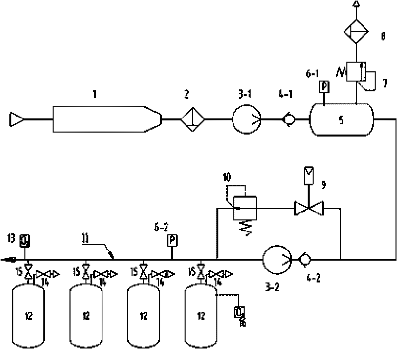
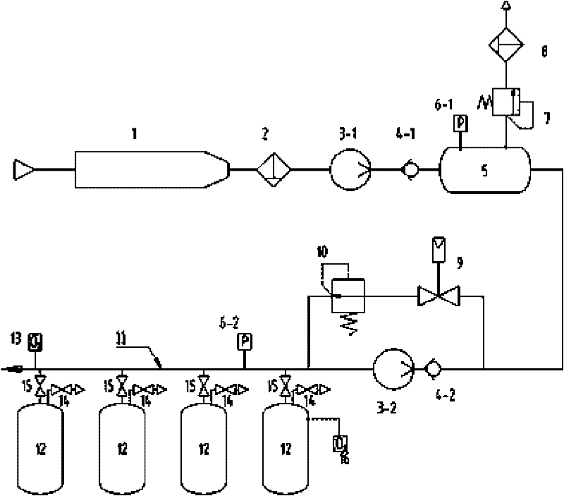
[0054] Such as figure 1 , an intrinsically safe oil storage tank inert protection device includes an inert gas generating device 1, a purification device 2, a buffer device 5, a breathing pipe network 11 and an electrical control device ( figure 1 Not shown in ), wherein the breathing pipe network 11 is communicated with a plurality of oil tanks 12 through an air inlet shut-off valve 15, and an exhaust shut-off valve 14 is installed on the oil tank to communicate with the outside atmosphere.

[0055]The inert gas generating device 1 can be a fuel inert gas generating device, and its inert gas outlet port communicates with the purifying device 2, and the outlet port of the purifying device 2 communicates with the first supercharging device 3-1, and the first supercharging device 3-1 communicates with the The inlet port of the first one-way valve 4 - 1 i...


PUM


Abstract

The invention discloses an intrinsically safe inerting protection method and an intrinsically safe inerting protection device for an oil storage tank, relates to a method and a device for active fire and explosion prevention of the oil storage tank, and aims to solve the problem of fire and explosion prevention of the oil storage tank. The method comprises the following steps: a, performing inerting on each oil tank in sequence to ensure that each oil tank achieves an inexplosive condition, namely, the oxygen concentration of gas in the tank is lower than 10 percent; b, detecting the pressure of a pipe network for supplying inert gas to the oil tank, and supplying the inert gas to the pipe network and inputting the inert gas to the oil tank through the pipe network if the pressure is lower than a set lower limit value; c, detecting the pressure of the pipe network for supplying the inert gas to the oil tank, emitting the inert gas in the pipe network if the pressure exceeds a set upper limit value; and d, detecting the oxygen concentration in the pipe network for supplying the inert gas to the oil tank, and repeating the step a if the concentration exceeds the set upper limit value. The device comprises a buffer device, an inlet end of which is to receive the inert gas, and an outlet end of which is connected to a breathing pipe network through a control valve; a first pressure transmitter mounted on the buffer device; the breathing pipe network communicated with the oil tank through an intake stop valve; a second pressure transmitter; an online oxygen analyzer mounted on the breathing pipe network; and an electric control device electrically connected to the first pressure transmitter, the second pressure transmitter, the online oxygen analyzer and the control valve.

Description

technical field [0001] The invention relates to an active fireproof and explosion-proof method and device for oil storage tanks, in particular to a method and device for fireproof and explosion-proof oil storage tanks using inertization technology. Background technique [0002] In the field of safety research, it is recognized that "inerting technology" is the most effective anti-explosion and anti-explosion technology, and "inerting technology" suitable for different purposes is a key topic of explosion-proof technology research at home and abroad and in various professional fields. When personnel are not the main purpose of protection, "active inerting technology" has been widely used. Such as oil tanker inert fire prevention and explosion protection, chemical production process inert protection, etc. [0003] "Inerting technology" is to inject a gas that replaces oxygen, such as carbon dioxide, nitrogen, inert gas and a mixture of the above gases, into a closed space wit...

Claims


Application Information

Patent Timeline
Patent Type & Authority Patents(China)
IPC IPC(8): B65D90/44B65D90/48B65D90/32B65D90/36B65D90/22F17D1/04
Inventor 杜扬汪映标钱海兵吴明军蒋新生周建忠王冬
Owner LOGISTICAL ENGINEERING UNIVERSITY OF PLA
Learn More