Electronic silicone oil fan clutch

An electronic silicone oil, clutch technology, applied in clutches, fluid clutches, machines/engines, etc., can solve the problems of limited operating temperature range, layout restrictions, slow response speed, etc., to achieve a wide range of temperature control, various control elements, and external influences small effect

Active Publication Date: 2010-07-07
WARNER SHENGLONG NINGBO CO LTD
View PDF4 Cites 14 Cited by
  • Summary
  • Abstract
  • Description
  • Claims
  • Application Information

AI Technical Summary

Problems solved by technology

[0007] However, the above-mentioned clutches all use temperature sensing parts to control the opening and closing of the valve plate, so there are the following disadvantages: first, the response speed is slow, and the thermal deformation speed of the bimetallic temperature sensing parts is slow; second, the control accuracy is low, and the quality of the temperature sensing parts is poor. Due to individual differences, the thermal deformation is not ideally linear; third, it is susceptible to environmental interference, and the temperature of the air blown from the radiator is affected by the ambient temperature and the distance from the radiator to the temperature sensing element; fourth, the layout is limited, in order to feel the heat dissipation The temperature of the sensor is limited, and the distance from the temperature sensor to the radiator is limited; fifth, the working temperature range is limited, and the thermal deformation of the temperature sensor is limited; sixth, the control element is single, and it can only be adjusted and controlled by the temperature of the radiator; seventh, Passive control can only be activated after the temperature of the radiator changes; eighth, only open-loop control can be realized; ninth, only fixed and simple control logic can be realized, which depends on the product structure, and the structure is fixed and cannot be too large. complicated
Refer to the publication of Chinese invention patent application: CN1807917A, which discloses a "Control Method of Externally Controlled Fan Clutch", this clutch can only be applied to engines above Euro III, and many engines cannot be used

Method used


Image

  • Electronic silicone oil fan clutch
  • Electronic silicone oil fan clutch
  • Electronic silicone oil fan clutch

Examples


Embodiment

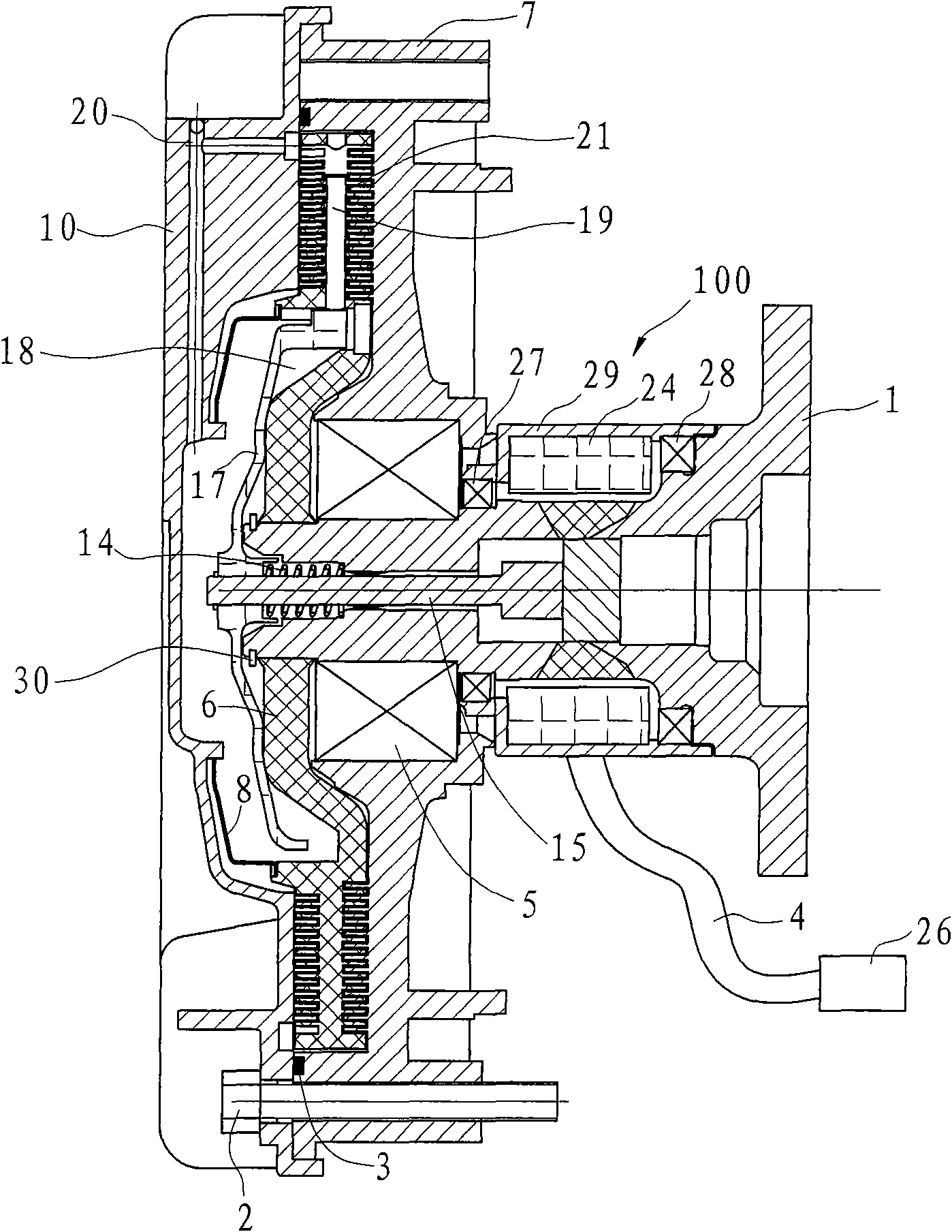
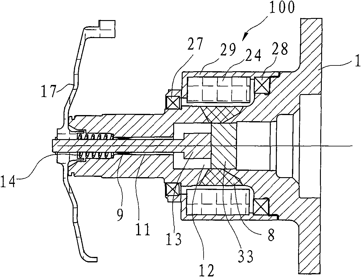
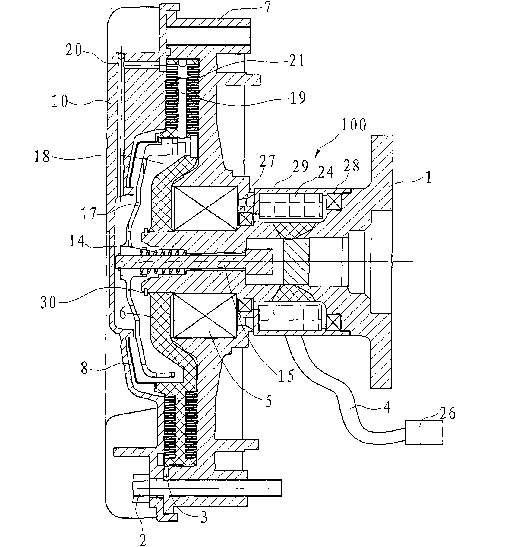
[0028] Example: such as figure 1 and figure 2 As shown, the electronic silicone oil fan clutch includes a housing 7, a front cover 10, a driving plate 6, a driving shaft 1, an oil storage cover 8, a valve ring 17, a push rod 15, a reset member 14, and a solenoid valve 100. There is an oil return hole 20, the driving shaft 1 is hollow, and the inner diameter of the front hollow portion 12 is larger than the inner diameter of the rear hollow portion 11, and the rear hollow portion 11 of the driving shaft is provided with a positioning ring 9 for constraining the push rod 15.

[0029] The housing 7 and the active plate 6 are arranged on the driving shaft 1, the active plate 6 is limited on the driving shaft 1 by a snap ring 30, the active plate 6 is provided with an oil outlet 19, and the housing 7 and the front cover 10 are used for The screw 2 is fixed and sealed with the sealing ring 3. The front cover 10 and the housing 7 form an engaging cavity 21 , and the oil storage ca...


PUM


Abstract

An electronic silicone oil fan clutch comprises a shell, a front cover, an oil storage cover, a driving shaft plugged in the shell and a driving board arranged on the driving shaft, and is characterized by also comprising a valve ring, a mandril, a resetting member and an electromagnetic valve; the valve ring is fixed on the tail of the mandril, axially penetrates through the hollow driving shaft and moves back and forth; the electromagnetic valve is connected with an engine electronic control unit by a wire bundle, generates magnetic field after powered up to suck the mandril to move forwards to realize control on openness degree of the oil outlet hole by the valve ring. Compared with the prior art, the invention has the advantages that various information is collected by the electronic control unit through preset parameters, according to the magnitude of current transmitted by the electronic control unit, the clutch generates a magnetic field corresponding to the magnitude, so that the mandril drives the valve block to move to realize connection and disconnection of silicone oil between an oil storage cavity and a meshing cavity, thus being capable of notifying in advance, and having the advantages of fast response, little influence by external, diverse control factors and high control preciseness.

Description

technical field [0001] The invention relates to an engine cooling system assembly, in particular to an electronic silicon oil fan clutch. Background technique [0002] Saving energy is a long-term policy of the country's economic development. According to relevant research data, 5-10% of the energy of the car is consumed by the fan cooling of the engine. In fact, the car does not need fan cooling for most of the working time, and generally only 5-10% of the time requires fan cooling. The fan automatic clutch technology is an important key technology for automobile energy saving. For this reason, many technicians have carried out technical improvements to the fan automatic clutch. They generally adopt the structure of bimetallic temperature sensing parts, through which the bimetallic temperature sensing parts feel the temperature of the air blown from the radiator to produce thermal deformation to control the switch of the valve. [0003] The existing silicon oil fan clutch...

Claims


Application Information

Patent Timeline
Patent Type & Authority Applications(China)
IPC IPC(8): F01P7/12F16D35/00
Inventor 戴宏鸣崔华南
Owner WARNER SHENGLONG NINGBO CO LTD
Why Eureka
Try Eureka