IC (integrated circuit) assembly burn-in equipment and IC heating device used by same

A heating device and burn-in technology, applied in the direction of electronic circuit testing, etc., can solve the problems of exposed and broken wire cores, time-consuming and cost-consuming, unreliable test results, etc., to achieve easy maintenance, improve stability, and reduce heat dissipation. Effect

Active Publication Date: 2010-07-07
KING YUAN ELECTRONICS
View PDF3 Cites 10 Cited by
  • Summary
  • Abstract
  • Description
  • Claims
  • Application Information

AI Technical Summary

Problems solved by technology

[0003] However, the current connection structure between the IC heater and the test slot is generally a clamshell structure with a single pivot, and the IC heater is placed on the upper cover, and the heating rod and temperature sensor in the IC heater need to reuse wires connected to the test board
After long-term use, it is found that the upper cover with IC heater is easy to cause the insulation layer of the wire to wear and tear due to repeated switching, resulting in the exposed core of the wire inside the wire.
In addition, in the actual operation of the one-sided hinged cover structure, in order to facilitate the manual operation of the upper cover to detect the IC, a space for manual operation is deliberately left around the test board; however, this space is easy Air convection causes the heat source of the IC heater to change due to air convection, making the heating temperature of the IC unstable, resulting in unreliable test results, and even having to retest, resulting in time-consuming and expensive

Method used


Image

  • IC (integrated circuit) assembly burn-in equipment and IC heating device used by same
  • IC (integrated circuit) assembly burn-in equipment and IC heating device used by same
  • IC (integrated circuit) assembly burn-in equipment and IC heating device used by same

Examples


Embodiment Construction

[0018] Because the present invention provides a kind of burn-in equipment required for burn-in test and the IC heating device used therein, the basic principle of the burn-in test used therein has been understood by those with ordinary knowledge in the relevant technical field , so the description below will not be fully described. At the same time, the drawings compared below are schematic structural representations related to the features of the present invention, and are not and need not be completely drawn based on actual dimensions, and are described in advance.

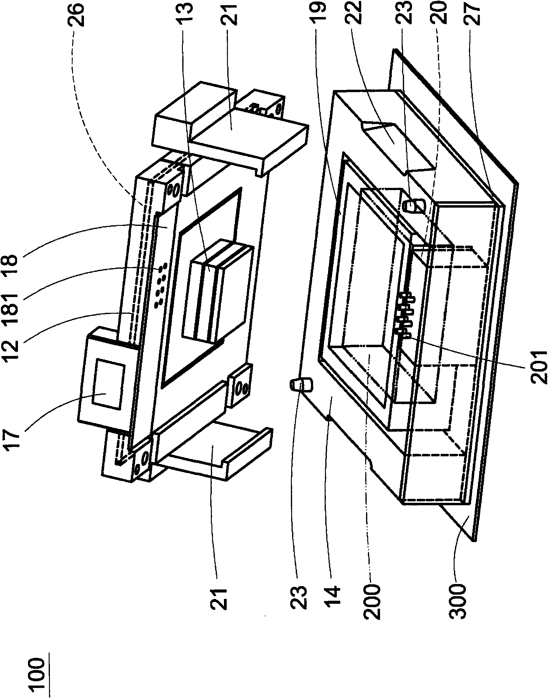
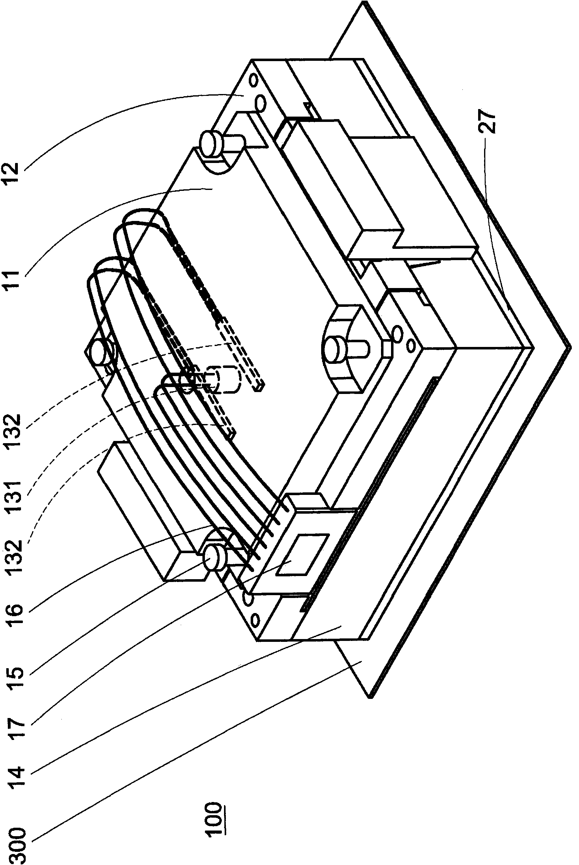
[0019] First please refer to Figure 1A and Figure 1B , which is the first preferred embodiment provided according to the present invention, is a three-dimensional schematic diagram of an IC heating device 100, which is used for the burn-in test of IC 200, and mainly includes an upper cover plate 11, a fixing seat 12, and a heating block 13 with base 14. The inside of the heating block 13 accommodates at leas...


PUM


Abstract

The invention provides IC (integrated circuit) assembly burn-in equipment and an IC heating device used by the same, wherein the IC heating device mainly comprises an upper cover plate, a fixing seat, a heating block and a base; the heating block is used for providing a heating surface close to uniformity so as to contact a measured IC; a heater and temperature inductor are accommodated in the heating block and electrically connected to a connector by utilizing a plurality of leads; the bottom of the connector is provided with a circuit board and a plurality of first connection points; an accommodating seat is arranged below the heating block for placing the measured IC; a part near the accommodating seat and corresponding to the circuit board is provided with a connecting seat; and the connecting seat is provided with a plurality of second connection points for correspondingly contacting and being conducted to the plurality of first connection points of the circuit board.

Description

technical field [0001] The present invention relates to a heating device, in particular to a burn-in device used in integrated circuit assembly (IC) burn-in test and the heating device used therein. Background technique [0002] After the packaged integrated circuit device (IC) is still required to conduct an electrical test at a preset high temperature to understand its stability, this procedure is usually called burn-in. During the burn-in procedure, it is necessary to heat and control the temperature of the IC under test, sensors, and other related components. This heating system has been widely implemented for many years. This system usually includes a heater, a temperature sensor, and a comparison measuring device. According to the difference between the voltage measured by the temperature sensor and a reference voltage, the difference is compared, and according to The difference between the two voltages is proportional to provide energy to a heater, and then the diffe...

Claims


Application Information

Patent Timeline
Patent Type & Authority Applications(China)
IPC IPC(8): G01R31/28
Inventor 刘大纲汤永仁林宗毅温进光李欣哲
Owner KING YUAN ELECTRONICS
Why Eureka
Try Eureka