Method for preventing connection point of cable lug and knife switch from overheating during current carrying

A technology for cables and connection points, which is applied in the field of contact systems of high-voltage transmission lines, can solve problems such as increased contact resistance, impact on operation safety, and large energy loss.

Inactive Publication Date: 2010-07-07
HANZHONG POWER SUPPLY BUREAU
View PDF0 Cites 1 Cited by
  • Summary
  • Abstract
  • Description
  • Claims
  • Application Information

AI Technical Summary

Problems solved by technology

Although the commercially available cable lug matches the cable section and the current carrying capacity meets the requirements, due to the limited bottom area of ​​the lug, the contact between the lug and the connecting plate is only on one side, and the current transmission is only between the lug of the cable and the connecting plate. As the weather changes and the current-carrying operation lasts for a long time, a slight deformation will appear at the connection, the two contact surfaces will gradually separate, the current channel will become smaller, the contact resistance will increase, and the contact overheating will naturally occur. , especially in the hot summer, when the load reaches more than half of the rated capacity, excessive energy loss may occur, causing dangerous overheating of the contacts and affecting operational safety.
However, as far as this problem is concerned, there is no better solution

Method used


Image

  • Method for preventing connection point of cable lug and knife switch from overheating during current carrying
  • Method for preventing connection point of cable lug and knife switch from overheating during current carrying
  • Method for preventing connection point of cable lug and knife switch from overheating during current carrying

Examples


Embodiment Construction

[0010] The present invention will be further described below in conjunction with the accompanying drawings.

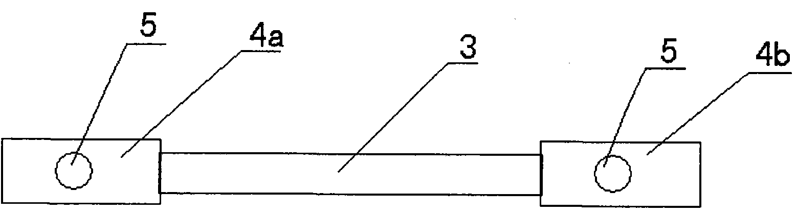
[0011] Such as figure 2 As shown, the bypass conductive strip is composed of a copper ribbon 3 and two bypass conductive strip lugs 4a, 4b, and the two bypass conductive strip lugs 4a, 4b are fixedly connected to both ends of the copper ribbon 3 respectively. This kind of bypass conductive belt is easy to make on site, as long as the copper ribbon of about 15cm is connected with two wire lugs.

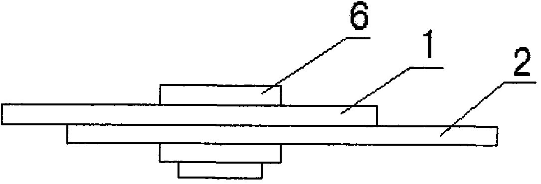
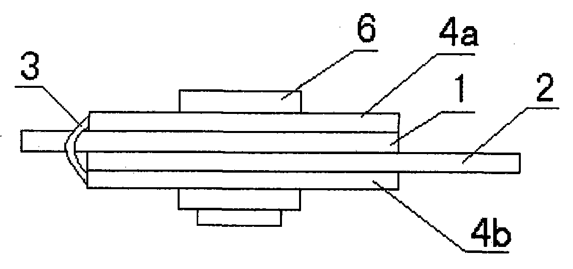
[0012] Such as image 3 As shown, the method of the present invention to prevent the overheating of the connection point between the cable lug and the knife switch is to add a connection point such as figure 2 Bypass conductive strips shown. The wire lug 4a at one end of the bypass conductive belt is located above the cable lug 1, and the other end of the lug 4b is located under the knife-type terminal board 2. The screw rod of the bolt 6 passes through the bolt hole 5 ali...


PUM


Abstract

The invention discloses a method for preventing a connection point of a cable lug and a knife switch from overheating during current carrying. The method is characterized in that a bypass conductive belt is arranged on the connection point of the cable lug and a knife switch type terminal board; and one end of the bypass conductive belt contacts the upper surface of the cable lug to form electrical connection, and the other end contacts the lower surface of the knife switch type terminal board form electrical connection. The method not only enlarges the contact area of the cable lug and the knife switch type terminal board but also increases current channels of connection point, thereby more uniformly distributing load current, reducing contact resistance and effectively preventing the connection point of the cable lug and the knife switch from overheating in the process of current carrying operation. The invention has the advantages of simple method, easy manufacture of the bypass conductive belt, no change of the original structure of electrical equipment during construction and convenient field construction.

Description

technical field [0001] The invention relates to a contact system of a high-voltage transmission line, in particular to a method for preventing overheating of a connection point between a cable lug and a knife switch during current-carrying operation. Background technique [0002] At present, the contact form of the power network is that the cable end lug and the knife-type terminal board of the power receiving / power receiving end equipment are fastened and connected by bolts (such as figure 1 shown). This kind of contact is simple and easy to operate, but over time, the contact will loosen, the contact surface will be oxidized, fouled, the effective contact point at the contact will be reduced, overheating, and even sparking. Tracing it to its cause, this is due to the current contact form. Although the commercially available cable lug matches the cable section and the current carrying capacity meets the requirements, due to the limited bottom area of ​​the lug, the contac...

Claims


Application Information

Patent Timeline
Patent Type & Authority Applications(China)
IPC IPC(8): H01H31/02H01H1/58
Inventor 李义仓李石陈郭力
Owner HANZHONG POWER SUPPLY BUREAU
Why Eureka
Try Eureka