Tundish with baffle wall for vacuum cast ingot

A tundish and slag retaining weir technology, used in foundry equipment, casting melt containers, metal processing equipment, etc., can solve the problems of short residence time, unreasonable temperature distribution, affecting product quality, etc., to increase residence time, promote The effect of floating inclusions and reducing the probability of slag entrainment

Active Publication Date: 2010-07-14
CHINA FIRST HEAVY IND
View PDF0 Cites 16 Cited by
  • Summary
  • Abstract
  • Description
  • Claims
  • Application Information

AI Technical Summary

Problems solved by technology

[0005] The residence time of the molten steel in the tundish is short, the temperature distribution is unreasonable, and the inclusions in the molten steel are easily brought into the ingot mold by the molten steel through the pouring inlet, which affects the product quality

Method used


Image

  • Tundish with baffle wall for vacuum cast ingot
  • Tundish with baffle wall for vacuum cast ingot
  • Tundish with baffle wall for vacuum cast ingot

Examples


Embodiment 1

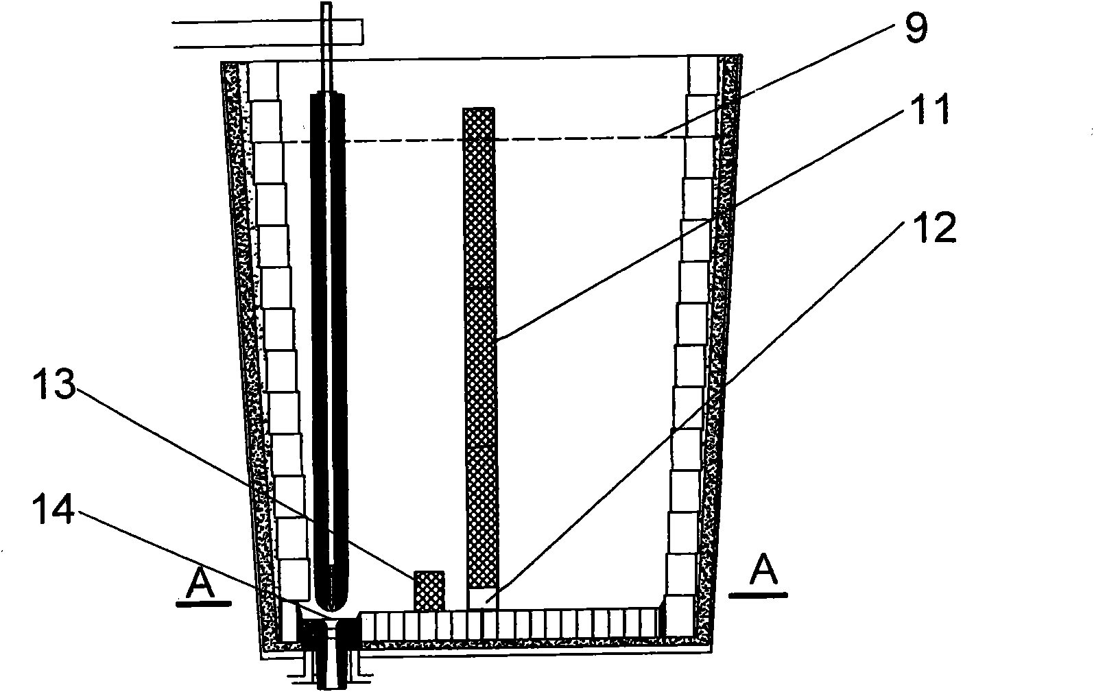
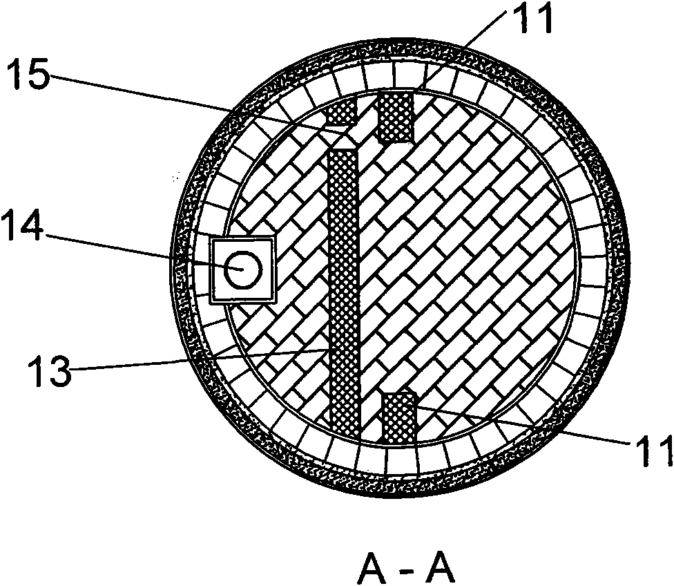
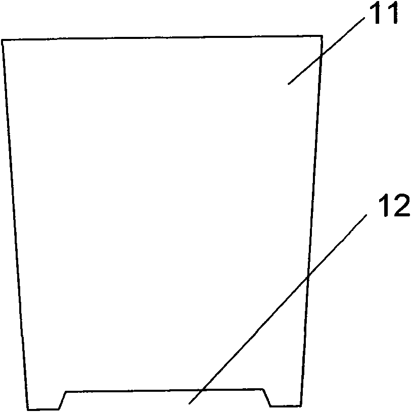
[0028] like figure 1 As shown, the structure of the tundish for vacuum ingot casting with a slag retaining weir of the present invention is that a slag retaining weir 11 is provided in the tundish, a steel passage 12 is provided at the bottom of the slag retaining weir 11, and the tundish The nozzle 14 is located on one side of the slag retaining weir 11 , the pouring steel inlet is located on the other side of the slag retaining weir 11 , and the height of the slag retaining weir 11 is greater than the liquid steel surface 9 . Wherein, the structure of the slag retaining weir 11 is as follows: image 3 As shown, that is, the slag retaining weir 11 is a "door" type slag retaining weir 11, the lower end of the slag retaining weir 11 extends to the bottom of the tundish on both sides, and a steel passage 12 is provided in the middle, and on the side of the nozzle 14 A diversion dam 13 is arranged on the bottom surface of the tundish, and the diversion dam 13 is higher than the ...

Embodiment 2

[0033] Another embodiment of the present invention is as Figure 5-7 As shown, the same reference numerals are used for the same parts as in the first embodiment.

[0034] Compared with the first embodiment above, this embodiment differs in that the structure of the slag retaining weir 111 is different.

[0035] like Figure 7 As shown, in this embodiment, the slag weir 111 of the tundish for vacuum ingot casting with a slag weir is a trapezoidal slag weir 111, and the bottom of the slag weir 111 is flush, and the Bottom surface offers steel channel 12.

Embodiment 3

[0037] Figure 8-10 Still another embodiment of the present invention is shown.

[0038] The structure of the tundish for vacuum ingot casting with a slag retaining weir in this embodiment is that a slag retaining weir 21 is arranged in the tundish, a steel passage 22 is provided at the bottom of the slag retaining weir 21, and a tundish nozzle 24 It is located on one side of the slag weir 21, and the pouring steel inlet is located on the other side of the slag weir 21. The height of the slag weir 21 is greater than the liquid steel level 9, and the lower end of the slag weir 21 extends to the bottom of the tundish. The slag weir 21 is at a certain distance from the bottom of the tundish, and there is a steel passage 22. The opening of the steel passage 22 on the pouring side is lower than the opening of the steel passage 22 on the nozzle 24 side, and the molten steel flows through the steel passage. Behind the channel 22, an oblique upward flow field is formed.

[0039] The...


PUM


Abstract

The invention discloses a tundish with a baffle wall for a vacuum cast ingot, belonging to the technical field of vacuum cast ingot. A baffle wall is arranged in the tundish, and the bottom of the baffle wall is provided with a steel channel; the bottom surface of the tundish on the water gap side is provided with a training wall which is higher than the upper top surface of the steel channel; and after passing through the steel channel and the training wall, molten steel forms a flow field inclining upwards. The tundish with a baffle wall for a vacuum cast ingot is characterized in that the baffle wall and the training wall are arranged in the tundish during vacuum ingot casting, which controls and improves the molten steel flowing mode in the tundish, relatively prolongs the retention period of molten steel in the tundish, prevents the tundish water gap from entrapping slag, provides favorable conditions for floating and removing impurities in molten steel, and improves the internal quality of the steel ingot.

Description

technical field [0001] The invention relates to the technical field of vacuum ingot casting, in particular to a tundish for vacuum ingot casting. Background technique [0002] The tundish is a device located between the ladle and the vacuum chamber for pouring molten steel. The tundish used for vacuum ingot casting is different from the tundish of the continuous casting machine in the metallurgical industry. It is cylindrical in shape and its main function is to realize the vacuum chamber. Sealing, storage of molten steel, steady flow and other functions. [0003] However, the existing middleware has the following disadvantages: [0004] When pouring molten steel into the tundish, the flow of molten steel is concentrated at the bottom of the tundish, and the fluctuations formed on the surface of the molten steel will form slag. [0005] The residence time of the molten steel in the tundish is short, the temperature distribution is unreasonable, and the inclusions in the mo...

Claims


Application Information

Patent Timeline
Patent Type & Authority Applications(China)
IPC IPC(8): B22D41/00
Inventor 赵林刘海澜王宝忠张凤喜高建军徐太安乔世章崔成万
Owner CHINA FIRST HEAVY IND
Why Eureka
Try Eureka