Method for measuring optical phase by using synchronous phase-shifting interference method and implementing light path

A technology of optical phase and synchronous phase shifting, which is applied in the direction of measuring optics, optics, measuring devices, etc., can solve the problems of high cost and high production process requirements, and achieve the effect of easy use, clear principle and simple method

Inactive Publication Date: 2010-07-14
BEIJING UNIV OF TECH
View PDF0 Cites 24 Cited by
  • Summary
  • Abstract
  • Description
  • Claims
  • Application Information

AI Technical Summary

Problems solved by technology

However, due to the use of holographic gratings for light splitting, in order not to appear unnecessary diffracted light and not to change the wavefront of incident light, the requirements for the grating manufacturing process are relatively high, so the overall cost of this type of interferometer is relatively high

Method used


Image

  • Method for measuring optical phase by using synchronous phase-shifting interference method and implementing light path
  • Method for measuring optical phase by using synchronous phase-shifting interference method and implementing light path

Examples


Embodiment

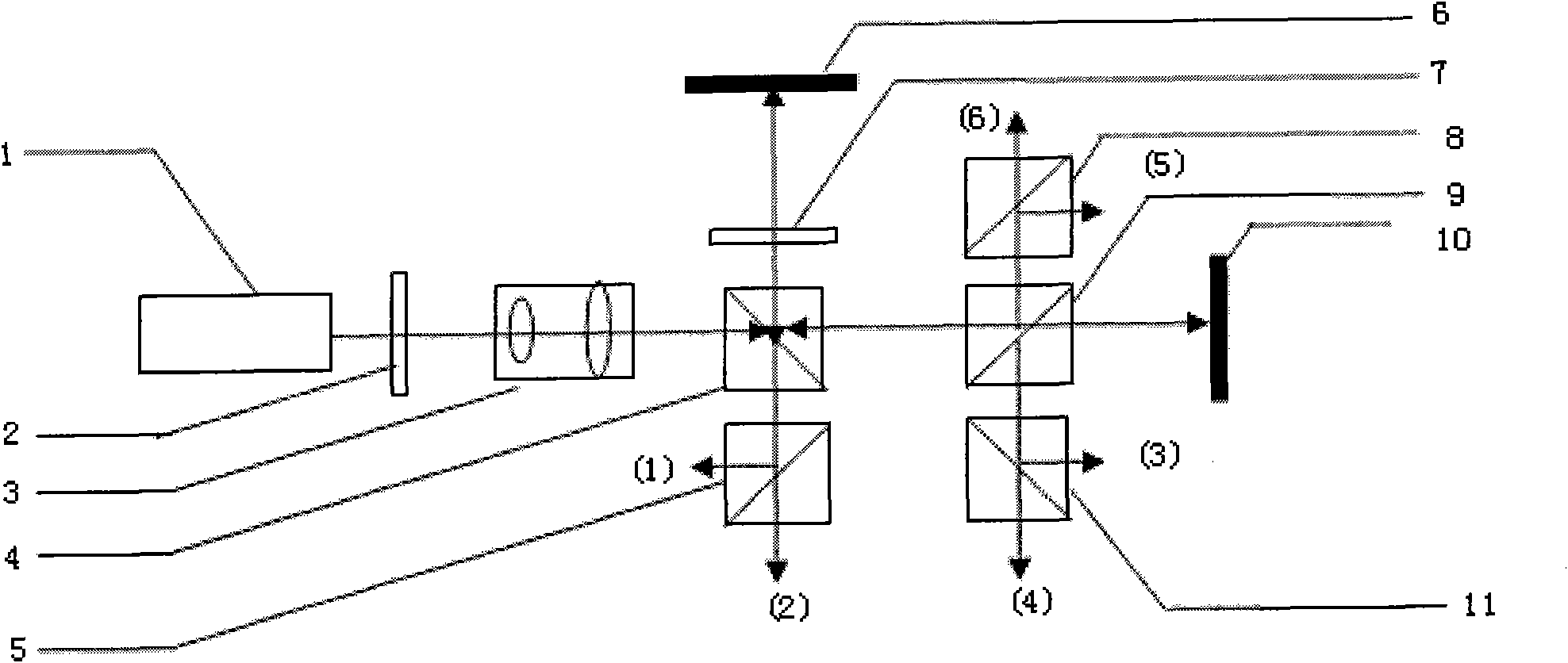
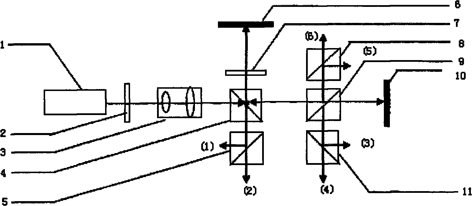
[0012] Example: such as figure 1 As shown, the frequency-stabilized laser 1 outputs linearly polarized laser light, uses the half-wave plate 2 to adjust its vibration transmission direction to the horizontal direction, and then expands the laser beam to the linearly polarized plane light source through the beam expander system 3, and then guides the laser beam into A polarization interference system composed of inverse prisms 4, 9 and polarization beam splitters 5, 8, 11. Each component is placed on the optical platform through an adjustable optical bench, and the optical path of each component is adjusted to the same horizontal plane. Wherein, the beam expander system 3 is made up of two convex lenses whose focal lengths are respectively 5cm and 8cm. Two rectangular prisms of anti-prism 4,9 adopt different mediums, so that there is a half-wave loss in the reflected light incident from the upper surface of semi-transparent half-reflective prism 4, and the incident reflected l...


PUM


Abstract

The invention discloses a method for acquiring an optical phase by using a synchronous phase-shifting interference method and an implementing light path, and relates to a method and a device for dynamically detecting wave surface information. According to the method, a light source is split into six beams by adopting a semi-transparent semi-reflective prism and a polarizing beam splitter prism, and meanwhile a polarizing interference method is combined to acquire six synchronous phase-shifting interference fringe patterns at one time in an air space, wherein the six interference fringe patterns are imaged on six CCD target surfaces respectively. The shape of a tested wave surface can be acquired by analyzing the six interference fringe patterns. Because the influence of vibration is consistent with the influence on the synchronous phase-shifting interference fringe patterns, the influence of the vibration can be eliminated by subtracting and deducting methods in a phase-shifting algorithm; therefore, the method is adaptive to high-precision wave surface measurement for more working environments, and does not need to perform PZT linear correction before each measurement. Moreover, the method is simple, the principle is clear, each component in the light path is easy to obtain, and the whole device is compact and easy to use.

Description

technical field [0001] The invention relates to a method and a device for dynamically detecting wavefront information, in particular to a method for obtaining an optical phase by using a synchronous phase-shifting interference method and realizing an optical path. Background technique [0002] In optical wavefront interferometry, the laser is usually used as a coherent light source, and two wavefronts are generated by dividing the amplitude. One wavefront is projected to the standard reference mirror and returned to form a reference wavefront, and the other wavefront is projected to the device under test and returned to form a reference wavefront. The test wavefront, the reference wavefront and the test wavefront meet in space to form an interference field, and the digital image acquisition device records the interference field in the form of an interference fringe pattern, and the shape of the test wavefront can be obtained by analyzing the interference fringe pattern. At p...

Claims


Application Information

Patent Timeline
Patent Type & Authority Applications(China)
IPC IPC(8): G01J9/02G02F1/21
Inventor 刘世炳贺雪鹏
Owner BEIJING UNIV OF TECH
Why Eureka
Try Eureka