Electromagnetic prospecting sending-receiving integration method and device

A technology of electromagnetic method and electric method, applied in the field of integration of electromagnetic transmission and inductive magnetic field detection, can solve the problems of large amplitude of primary field signal, difficulty in distinguishing secondary field, existence, etc.

Active Publication Date: 2010-07-14
CHONGQING CUILU DETECTION TECH CO LTD
View PDF1 Cites 26 Cited by
  • Summary
  • Abstract
  • Description
  • Claims
  • Application Information

AI Technical Summary

Problems solved by technology

[0004] (1) There is a mutual inductance between the sending coil and the receiving coil, and the signal induced by the receiving coil not only has a secondary field signal, but also aliases a primary field, and there is a problem of aliasing between the primary field and the secondary field;
[0005] (2) Because the amplitude of the primary field signal is large and the amplitude of the secondary field is small, it is very difficult to distinguish the secondary field in the background of the strong primary field. There is a large dynamic range of the received signal and it is difficult to receive weak secondary field signals question;
[0006] (3) The number of turns of the sending and receiving coils of the conventional small wire frame same-point device is large, and the mutual inductance is strongly affected, so it is difficult

Method used


Image

  • Electromagnetic prospecting sending-receiving integration method and device
  • Electromagnetic prospecting sending-receiving integration method and device
  • Electromagnetic prospecting sending-receiving integration method and device

Examples


Embodiment 1

[0160] Embodiment 1, applied to the time-domain electromagnetic method, is carried out in the following order:

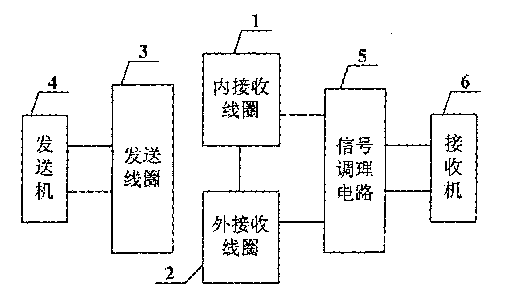
[0161] 1. Design of sending coil 3, inner receiving coil 1 and outer receiving coil 2:

[0162] according to Figure 5 As shown, the center point O is selected on the plane, and the transmitting coil 3 is designed to be a planar spiral coil with 18 turns. The initial radius of the innermost coil is 90.875mm, and the initial radius of other coils increases by 3.5mm in turn, and the line width is 2.5mm. The distance is 1mm;

[0163] The inner receiving coil 1 is designed to be a 12-turn planar spiral coil, the initial radius of the innermost coil is 69.5mm, the initial radius of the outermost coil is 80.5mm, the line width is 0.5mm, and the distance between lines is 0.5mm;

[0164] The outer receiving coil 2 is designed as a fan ring composed of 16 circular arcs. The inner radius of the outermost fan ring is 158mm, the outer radius is 220mm, and the separation dista...

Embodiment 2

[0190] Embodiment 2, applied to the frequency domain electromagnetic method, is carried out according to the following sequential steps:

[0191] 1, adopt the sending coil 3 of embodiment 1 design, inner receiving coil 1 and outer receiving coil 2, get by the 2nd step of embodiment 1

[0192] ψ 内1 =2.55300×10 -5 i(t)(Wb)

[0193] Get by the 3rd step of embodiment 1

[0194] ψ 外1 =-2.55158×10 -5 i(t)(Wb);

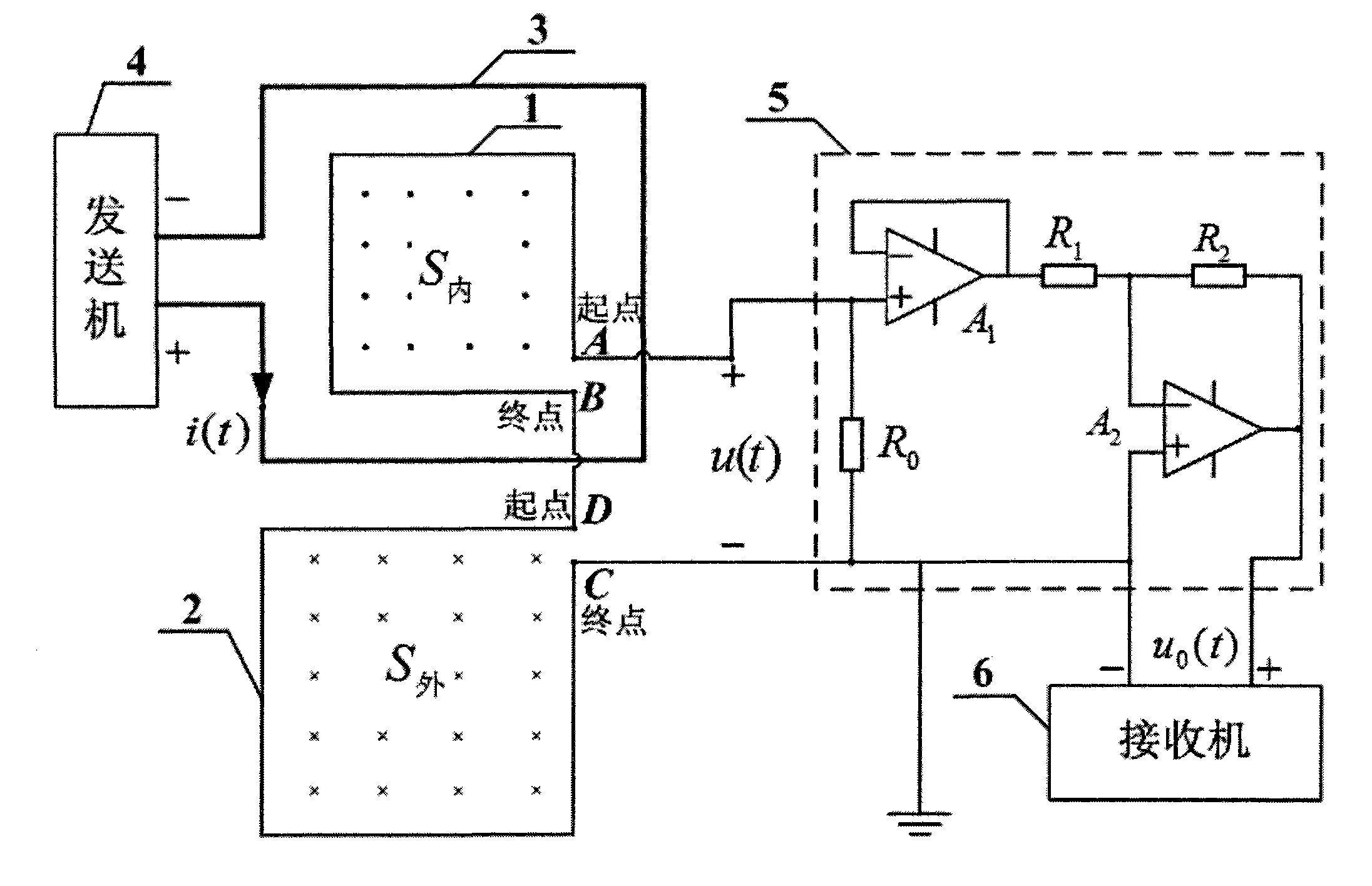
[0195] 2. Start the transmitter, send such as Figure 9 The sinusoidal current shown, in which the current waveform is measured by the current sensor, the conversion rate is 100mV / A, so the peak value of the current is 4.8A, and its frequency is 50Hz, which can be approximated by the sinusoidal current expression

[0196] i(t)=4.8sin(100πt)(A)

[0197] 3. Calculate the primary field induced voltage u of the inner receiving coil 1 AB1

[0198]

[0199] Get: u AB1 =38.5cos(100πt)(mV)

[0200] Calculate the primary field induced voltage u of the outer receiving c...

Embodiment 3

[0206] Embodiment 3, applied to the time-domain electromagnetic method, is carried out in the following order:

[0207] 1. Design of sending coil 3, inner receiving coil 1 and outer receiving coil 2:

[0208] according to Figure 12 As shown, the center point O is selected on the plane, and the transmitting coil 3 is designed to be a square solenoid with 8 turns; the side length of the square is 300mm, the line width is 2mm, and the distance between lines is 3mm;

[0209] The receiving coil 1 in the design is a 6-turn square solenoid; the side length of the square is 210mm, the line width is 2mm, and the distance between lines is 1.8mm;

[0210] Design the outer receiving coil 2 to be a ring composed of 8 non-closed squares, the side length of the inner ring is 350mm, and the side length of the outer ring is 780mm; the line width is 2mm, the distance between lines is 3mm, and the separation distance is 3mm;

[0211] 2. Calculate the magnetic flux ψ passing through the inner ...


PUM

PropertyMeasurementUnit
Line widthaaaaaaaaaa

Abstract

The invention relates to an electromagnetic prospecting sending-receiving integration method and a device. The invention is suitable for the fields of geophysical prospecting, engineering geological prospecting, underground military target detection, nondestructive inspection and the like. The technical scheme of the invention is as follows: arranging an inner receiving coil 1 in a sending coil 3; arranging an outer receiving coil 2 outside the sending coil 3; ensuring that magnetic flux passing through the inner receiving coil 1 and the outer receiving coil 2 is equivalent and is in opposite sign under the action of primary field; mutually offsetting primary field induced voltage; and only outputting a secondary field signal. The device comprises a transmitter 4, a sending coil 3, an inner receiving coil 1, an outer receiving coil 2, a signal conditioning circuit 5 and a receiver 6, wherein the inner receiving coil 1 is connected with the outer receiving coil 2, and the coil 1 and the coil 2 are connected with the signal conditioning circuit 5. The invention has the advantages of eliminating primary field influence, reducing signal dynamic range, expanding the practicability of small-wireframe same-point device and realizing integration of the sending coil and the receiving coil.

Description

technical field [0001] The invention relates to a method and device integrating electromagnetic transmission and inductive magnetic field detection, which is used in the electromagnetic method to detect the secondary field signal induced by the target body, and is suitable for geophysical exploration, engineering geological exploration, underground military target detection and Non-destructive testing and other fields. Background technique [0002] Electromagnetic exploration has been widely used in mineral exploration, engineering geological exploration, groundwater resources, underground pipelines and environmental geological exploration and other fields. Among them, frequency domain electromagnetic method and time domain electromagnetic method are commonly used. Electromagnetic transmitters are used to generate excitation primary fields. The secondary field induced by the geological body is collected by the receiver, and the structure of the geological body is detected by...

Claims


Application Information

Patent Timeline
IPC IPC(8): G01V3/10
Inventor 付志红张淮清陈文斌苏向丰王勇
Owner CHONGQING CUILU DETECTION TECH CO LTD
Why Eureka
Try Eureka