Conveying device for retrievable self-eject nervi cerebrales stent

A delivery device and self-elastic technology, applied in the field of medical devices, can solve problems such as difficulty in manufacturing and installation, and achieve the effects of reducing irritation and damage and accurately blocking

Inactive Publication Date: 2010-07-21
可大年
View PDF1 Cites 27 Cited by
  • Summary
  • Abstract
  • Description
  • Claims
  • Application Information

AI Technical Summary

Problems solved by technology

However, it is not only difficult to manufacture, but also difficult to install in a cranial nerve stent with an outer sheath size of 3F (1mm).

Method used


Image

  • Conveying device for retrievable self-eject nervi cerebrales stent
  • Conveying device for retrievable self-eject nervi cerebrales stent
  • Conveying device for retrievable self-eject nervi cerebrales stent

Examples


Embodiment 1

[0052] This embodiment is a delivery device for a retractable self-elastic cranial nerve stent with a stent fixing part and a developing mark.

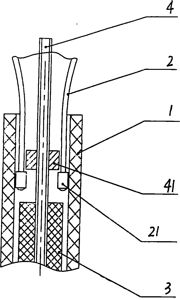
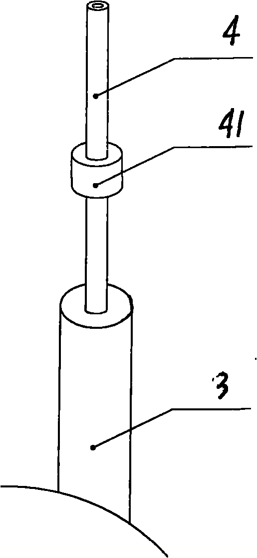
[0053] figure 1 , image 3 , Figure 7 As shown, a delivery device for a retractable self-elastic cranial nerve stent includes an outer sheath tube 1, an inner sheath tube and a self-elastic stent 2, wherein an inner sheath tube is slidably inserted into the outer sheath tube 1 , the length of the inner sheath tube is slightly longer than the outer sheath tube 1, and a self-elastic stent 2 in a compressed state is installed in the outer sheath tube 1, and the self-elastic stent 2 without membrane is located in front of the inner sheath tube, and the self-elastic stent 2 It is a ring column network structure, and the rear end of the self-elastic stent 2 is provided with more than one development mark 21 that plays a tracking role. The thickness of the development mark 21 is slightly greater than the thickness of the self-elastic sten...

Embodiment 2

[0071] This embodiment is a delivery device for a retractable self-elastic cranial nerve stent that is cooperating with the gear and the self-elastic stent for delivery and retraction.

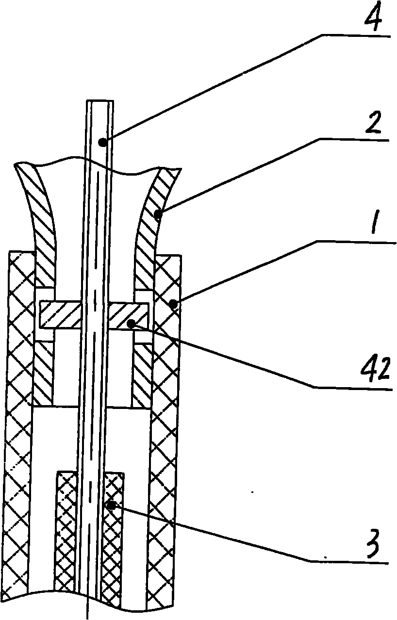
[0072] figure 2 , Figure 4 , Figure 5 , Figure 6 , Figure 7 , Figure 8 As shown, a delivery device for a retractable self-elastic cranial nerve stent includes an outer sheath tube 1, an inner sheath tube and a self-elastic stent 2, wherein an inner sheath tube is slidably inserted into the outer sheath tube 1 , the length of the inner sheath tube is slightly longer than the outer sheath tube 1, and a compressed self-elastic bracket 2 is installed in the outer sheath tube 1, and the self-elastic bracket 2 is located in front of the inner sheath tube, and the self-elastic bracket 2 is a ring Column network structure, the rear end of the self-elastic stent 2 is provided with a developing mark 21 which plays a tracking role, and the thickness of the developing mark 21 is slightly greate...


PUM


Abstract

The invention discloses a conveying device for a retrievable and self-eject nervi cerebrales stent. An inner sheath catheter is slidably sleeved in an outer sheath catheter; the length of the inner sheath catheter is a little bit longer than that of the outer sheath catheter; a self-eject stent which is in a compression state is arranged in the outer sheath catheter; the self-eject stent is positioned in the front of the inner sheath catheter and has a cylindrical net structure; a developing mark for tracking is arranged at the rear end of the self-eject stent, and the thickness of the developing mark is a little bit grater than that of the self-eject stent; the inner sheath catheter consists of a cylindrical stable sheath catheter and a core tube passing through the stable sheath catheter; and the stent fixed piece is matched with the developing mark or a gear is matched with a mesh to realize the retracement of the self-eject stent. The conveying device has the advantages that: 1, the self-eject stent can be invaginated into the outer sheath catheter for release again when the positioning of the self-eject stent is inaccurate; 2, the stimulus and injury to vascular walls in the conveying process are reduced; and 3, a structure is simple.

Description

technical field [0001] The invention relates to a delivery device for a self-elastic cranial nerve stent, which is used for the treatment of cerebrovascular stenosis or interventional treatment of cerebrovascular tumors, and belongs to the field of medical devices. Background technique [0002] 780,000 patients in the United States suffer from stroke each year. A stroke is caused when a blood vessel to the brain becomes blocked (anoxic stroke) or ruptures (hemorrhagic stroke), preventing part of the brain from getting the blood or oxygen it should, resulting in death. Hypoxic stroke was diagnosed in approximately 88% of cases, while hemorrhagic stroke was diagnosed in the remaining 12% of cases. [0003] The success of treating cardiovascular stenotic diseases with stents has led to further development of intracranial stents. Balloon-expandable stent devices may reduce the safety of intracranial vascular interventional procedures due to the flexibility of the delivery devi...

Claims


Application Information

Patent Timeline
Patent Type & Authority Applications(China)
IPC IPC(8): A61F2/84A61F2/966A61M29/00
CPCA61F2/915A61F2002/91525A61F2/95A61F2002/9665A61F2/966A61F2230/0054A61F2250/0098A61F2/07A61F2002/9505A61F2002/91558A61F2250/0018
Inventor 张一
Owner 可大年
Why Eureka
Try Eureka