Initiative exhaust method for injection mould and vacuum valve device for injection mould

A technology for injection molds and vacuum valves, applied in valve devices, valve operation/release devices, valve details, etc., can solve the problem of fewer injection molds, achieve the effects of prolonging life, improving filling effect, and speeding up injection speed

Inactive Publication Date: 2010-07-21
XIAMEN UNIV
View PDF1 Cites 12 Cited by
  • Summary
  • Abstract
  • Description
  • Claims
  • Application Information

AI Technical Summary

Problems solved by technology

So far, the method of actively venting injection molds has been rare

Method used


Image

  • Initiative exhaust method for injection mould and vacuum valve device for injection mould
  • Initiative exhaust method for injection mould and vacuum valve device for injection mould
  • Initiative exhaust method for injection mould and vacuum valve device for injection mould

Examples


Embodiment Construction

[0029] The following embodiments will further describe the present invention in detail in conjunction with the accompanying drawings.

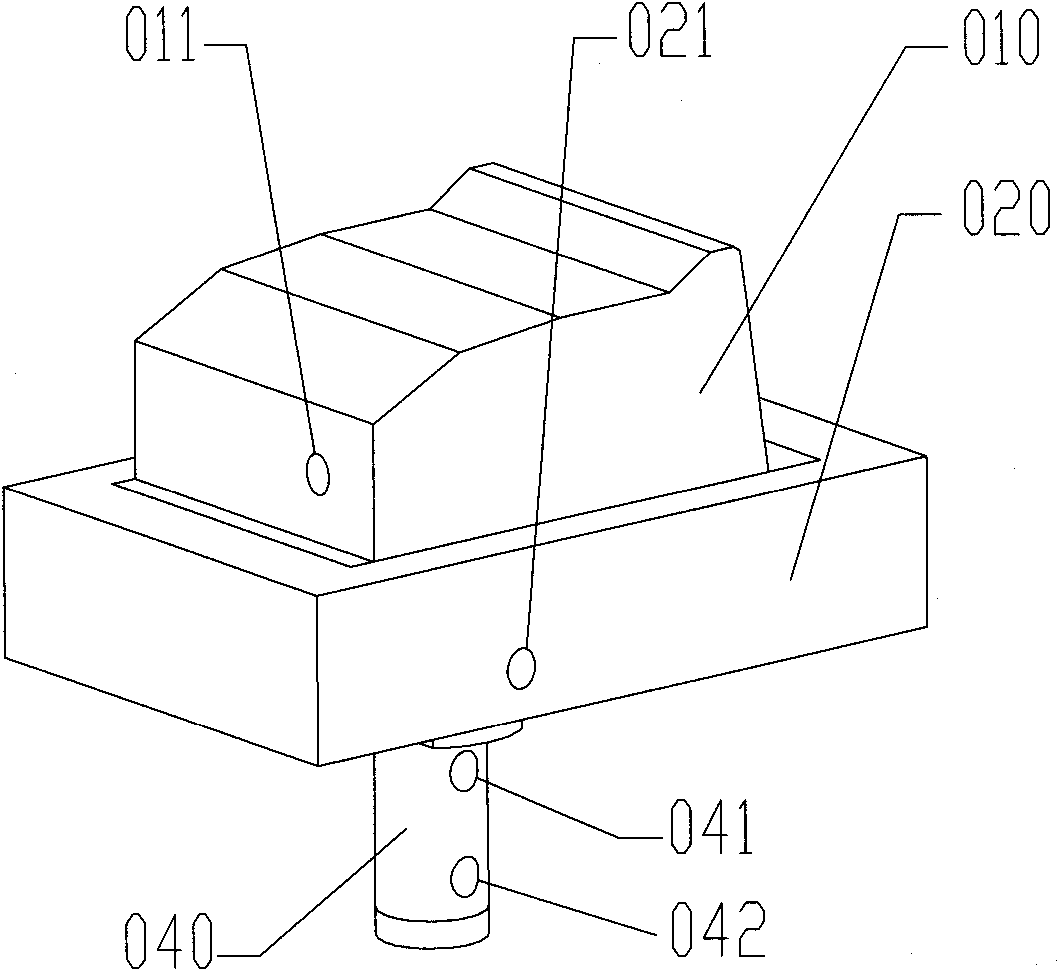
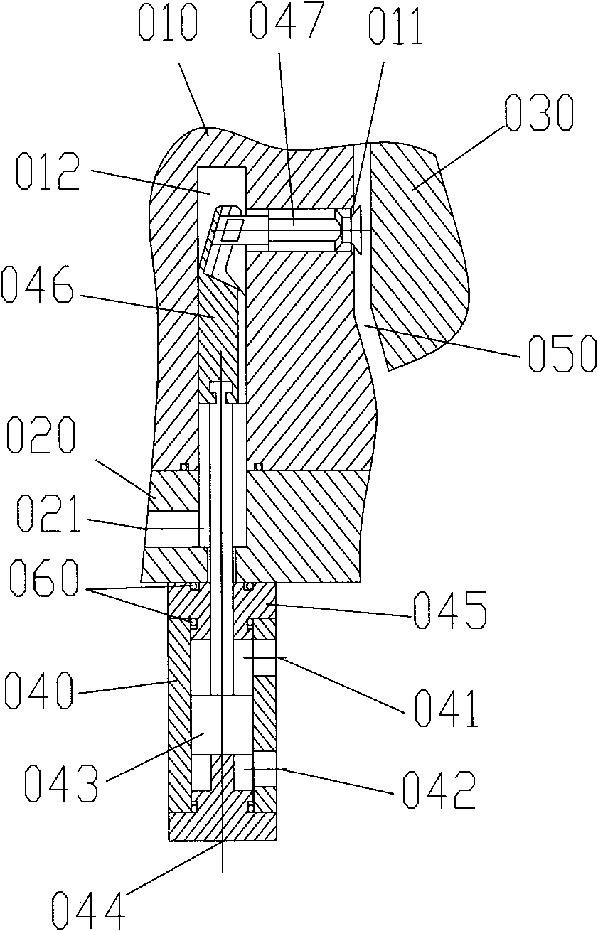
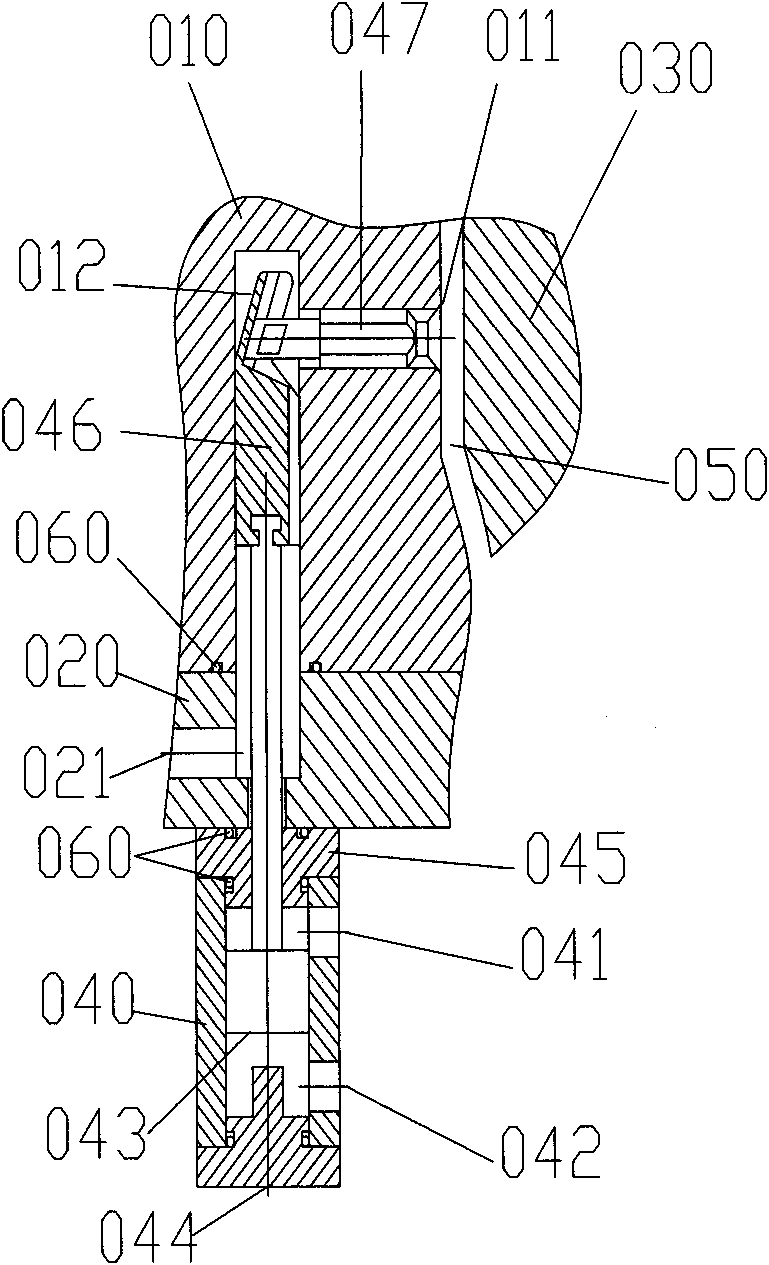
[0030] figure 1 with 2 The three-dimensional structural schematic diagram of the vacuum valve device for the injection mold described in the embodiment of the present invention assembled with the movable mold side and the partial cross-sectional view in the open state are given, Figure 4~6 The three-dimensional structure diagram of the valve core, the valve core control rod and the piston rod of the vacuum valve device for injection mold according to the embodiment of the present invention is given.

[0031] On the movable mold core 010, a circular valve hole 011 communicating with the cavity 050 is opened in the area where exhaust is required. The cavity 050 is a space formed by the movable mold core 010 and the fixed mold core 030. On the movable mold core 010, a rectangular guide hole 012 is opened perpendicular to the direction of the v...


PUM


Abstract

The invention relates to an initiative exhaust method for an injection mould and a vacuum valve device for the injection mould, relating to an injection mould. The vacuum valve device is provided with a valve core, a valve core control rod, a piston rod and a cylinder. After the mode locking of the injection mould, an external compressed air source is utilized to drive the vacuum valve device, an exhaust channel is opened, and then an external air extractor is communicated with the cavity of the injection mould through the exhaust channel. The external air extractor starts to work, the cavity of the injection mould is pumped to a negative pressure state, and then the external compressed air source is utilized to drive the vacuum valve device for the injection mould and close the exhaust channel. Fusing plastic is injected into the cavity, and after the exhaust channel of the vacuum valve is closed, air is continuously exhausted through a tiny gap between the vacuum valve device and the cavity of the injection mould. The injection mould is opened, and a moulding piece is taken out, the external compressed air source is utilized to carry out back flushing, and residues and impurities in the vacuum valve device for the injection mould and the exhaust channel are cleared. After the mould is closed, the next work circulation is performed.

Description

technical field [0001] The invention relates to an injection mold, in particular to an active exhaust method for the injection mold and a vacuum valve device for the injection mold. Background technique [0002] In the ordinary injection molding process, the existing exhaust method of the cavity of the injection mold is a passive exhaust method: the resin melt is gradually injected into the cavity of the injection mold, and the gas in the cavity is forced from the parting surface, Mold structures such as ejector pin gaps or specially opened exhaust grooves are discharged. For plastic parts with complex structures or thick walls, if the gas in the corresponding mold cavity cannot be exhausted smoothly, nesting, ablation, and pores may occur during the injection molding process, resulting in the scrapping of the plastic parts; for materials For plastic parts with poor fluidity or thin wall thickness, if the gas in the corresponding mold cavity cannot be exhausted smoothly, th...

Claims


Application Information

Patent Timeline
IPC IPC(8): B29C45/34F16K31/122
Inventor 葛晓宏黄红武范增伟吴立明
Owner XIAMEN UNIV
Why Eureka
Try Eureka