Heat treatment equipment and heat treatment method of metal parts
A technology of heat treatment equipment and heat treatment method, which is applied in tempering heat treatment equipment, heat treatment, and quenching fields. It can solve the problems of easy damage to the drum, low efficiency, waste of heating furnace, etc., and achieve the effect of simple lifting
- Summary
- Abstract
- Description
- Claims
- Application Information
AI Technical Summary
Problems solved by technology
Method used
Image
Examples
Embodiment 1
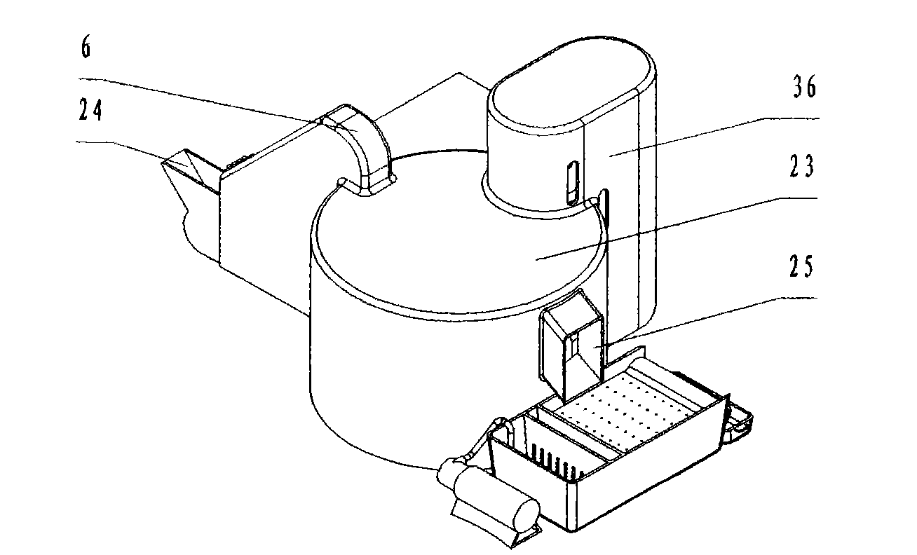
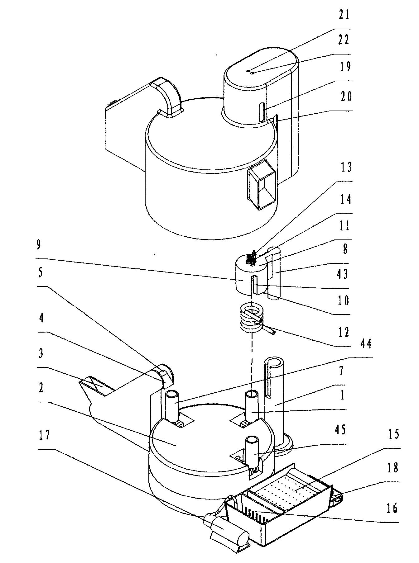
[0036] Such as figure 1 , figure 2 As shown, a heat treatment equipment for metal parts includes a feeding device, a material cylinder 1, a material cylinder 44, a material cylinder 45, a turntable 2, a turntable rotation mechanism (not shown), and a turntable limit for turning the turntable 2 to a set position. Mechanism (not shown), lifting mechanism, electromagnetic induction heating device, feeding device, feeding device.
[0037] The feeding device comprises a feed port 3, a discharge port 4 and a feed conveyor belt 5 connecting the feed port 3 and the discharge port 4, a conveyor belt driving device (not shown) and a cover 6, and the discharge port 4 is in the When the rotating disk 2 stops rotating, it is facing the inlet of one of the barrels 44 .
[0038] Material cylinder 1, material cylinder 44 and material cylinder 45 are installed on the turntable 2, and are evenly distributed along the circumference of the turntable 2. The turntable rotation mechanism is inst...
Embodiment 2
[0043] Such as image 3 , Figure 4 , Figure 5 As shown, different from Embodiment 1, the lifting platform 7 includes a lifting rod 8 installed on the lifting platform 7 and a lower supporting block 26 and an upper fixing block 27 fixed on the lifting rod 8, and the induction coil 12 is installed on the lower supporting block. 26 and the induction coil 12 is fixed between the lower support block 26 and the upper fixed block 27 by the upper fixed block 27, and the lower support block is provided with the air-avoiding hole 28 of the empty barrel; the upper fixed block seals the barrel; The fixed block is provided with a carbon and / or nitrogen injection port joint 29 and a gas port joint 30 .
[0044] The bottom of the barrel 1 is an open end. The unloading device includes a movable block 31 installed at the bottom of the barrel 1, an inverted groove 32, a drive motor 33 and an output gear 34, and the movable block 31 is provided with a rack 35 meshing with the output gear 34...
Embodiment 3
[0046] Such as Figure 6 As shown, the difference from Embodiment 1 is that there are two barrels, namely barrel 47 and barrel 48, and the lifting device relative to the barrel and the induction coil is a turntable lifting mechanism. The turntable lifting mechanism and the turntable rotation mechanism include a motor 37, a worm screw 38 coaxially installed with the motor, a worm wheel 39 engaged with the worm screw 38, and a screw 40 coaxially installed with the worm wheel 39, and the turntable 2 is installed on the screw 40. A base fixing seat 41 is also provided at the bottom of the turntable 2 . The cylinder 9 is fixed on the fixed rod 42 .
PUM
 Abstract
Description
Claims
Application Information
 - R&D
- Intellectual Property
- Life Sciences
- Materials
- Tech Scout
- Unparalleled Data Quality
- Higher Quality Content
- 60% Fewer Hallucinations
Browse by: Latest US Patents, China's latest patents, Technical Efficacy Thesaurus, Application Domain, Technology Topic, Popular Technical Reports.
© 2025 PatSnap. All rights reserved.Legal|Privacy policy|Modern Slavery Act Transparency Statement|Sitemap|About US| Contact US: help@patsnap.com


