Method and apparatus for continuous thermal treatment of steel strip

A technology for heat treatment chambers and steel strips, applied in heat treatment equipment, heat treatment furnaces, hot-dip coating processes, etc., can solve problems such as energy consumption and complicated stamping equipment

Active Publication Date: 2016-07-20
FIVES STEIN SA
View PDF31 Cites 8 Cited by
  • Summary
  • Abstract
  • Description
  • Claims
  • Application Information

AI Technical Summary

Problems solved by technology

With this method, the annealing and galvanizing operations can be carried out using tools according to the prior art, however the stamping equipment is particularly complex and requires reheating of the steel sheets, which likewise consumes energy

Method used


Image

  • Method and apparatus for continuous thermal treatment of steel strip
  • Method and apparatus for continuous thermal treatment of steel strip
  • Method and apparatus for continuous thermal treatment of steel strip

Examples


Embodiment Construction

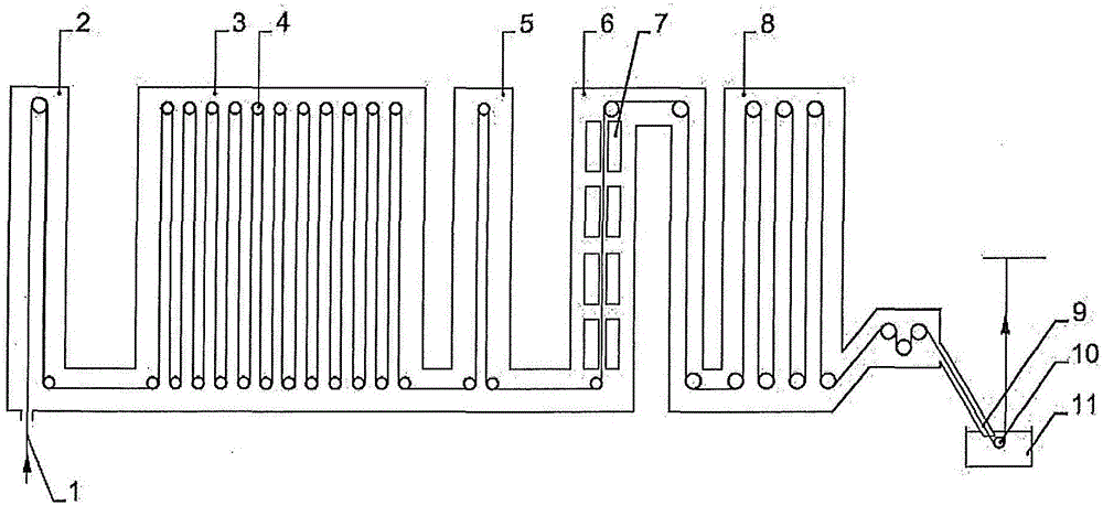
[0052] figure 1 A vertical annealing-galvanizing line according to the prior art is shown. It is understood that the same method can be implemented in a horizontal pipeline.

[0053] The steel strip 1 passes through the preheating chamber 2 and the heating chamber 3 on the roller assembly 4 successively. In this example, the strip then passes through chamber 5 corresponding to slow cooling, chamber 6 corresponding to conventional or rapid cooling by spraying gas over the strip by cooling box 7 , and chamber 8 as holding chamber. The strip is brought into the atmosphere 9 by a gaine and one of the ends of the strip is dipped in a pool of molten zinc or metal 11 by means of rollers 10 .

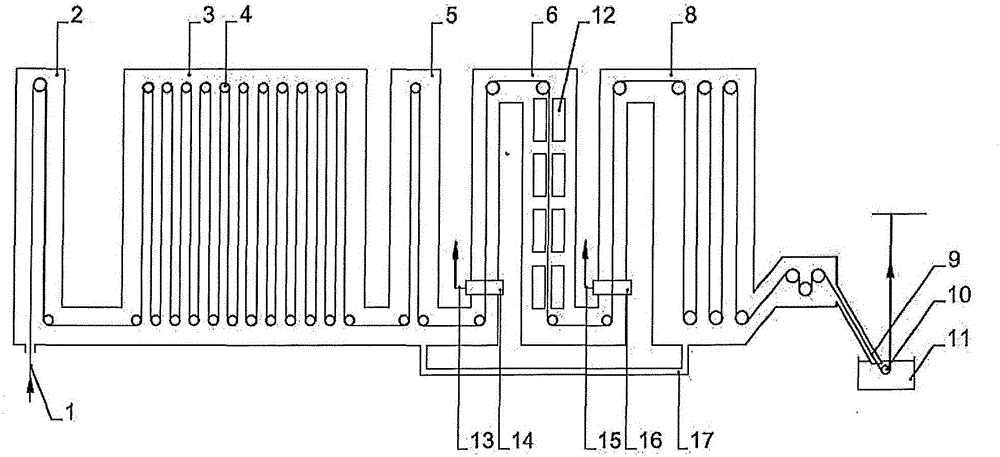
[0054] The rapid cooling chamber by spraying of liquid on the belt is separated from the upstream and downstream chambers of the furnace by an atmospheric compartment. In order to use the method according to the invention, in particular by using the cabins 14, 17 as described in FR2903122 ( ...


PUM


Abstract

The invention relates to a method for continuous thermal treatment of a steel strip wherein: the steel strip passes through consecutive thermal treatment chambers; the steel strip is quickly cooled, in particular at more than 200 DEG C / sec, in at least one of the chambers by spraying liquid onto the steel strip, or by spraying a fluid made up of gas and liquid or spraying a combination of gas and liquid forming a mist; and, after the quick cooling, a protective metal layer is deposited on the steel strip by dip coating. The fluid sprayed for cooling the steel strip is a fluid with properties for acid-washing iron oxides or other alloy elements contained in the steel to be treated, in order to minimise the oxidation of the steel strip and reduce the oxides that may have formed on the steel strip such as to reduce or eliminate surface defects during the dip-coating operation. The fluid is sprayed at a pressure and at a distance from the steel strip such that the combined effect of the acid-washing property and the mechanical action of the sprayed fluid reduces the layer of oxides on the surface of the steel strip. The temperature of the steel strip at the end of the cooling step is the temperature necessary for carrying out the desired treatment cycle, in particular between 200 DEG C to 750 DEG C, typically higher than 200 DEG C.

Description

technical field [0001] The present invention relates to an annealing furnace on a continuous heat treatment line for metal strip, mainly steel sheets, where the annealing cycle uses a cooling ramp. [0002] The method is particularly suitable for hot-dip galvanizing lines or lines involving a combination of annealing and hot-dip galvanizing. [0003] The corresponding method and device according to the invention make it possible to carry out a heat treatment cycle comprising rapid wet cooling while at the same time enabling the production of new steel, which does not require pickling of the strip after the heat treatment. Background technique [0004] Existing continuous annealing lines for metal strip, mainly steel strip, consist of successive chambers in which the strip is first heated, then held at temperature for a variable period of time, and finally cooled almost to ambient temperature, to Capable of being commercialized or subjected to post-processing. For more comp...

Claims


Application Information

Patent Timeline
Patent Type & Authority Applications(China)
IPC IPC(8): C21D9/573C23C2/02C21D1/667C23F17/00C23G3/02
CPCC21D9/573C21D1/60C21D1/667C23G1/08C23G1/088C23G3/023C23G3/027C23G3/028C23C2/0038C23C2/024C21D9/0062C21D6/00C21D9/52C21D9/563C21D9/5737C21D9/68C23C2/06C23C2/40
Inventor A·热诺
Owner FIVES STEIN SA
Why Eureka
Try Eureka