Lamella heat exchanger and manufacturing method thereof and lamella evaporative condensing equipment

A technology of condensing equipment and heat exchangers, which is applied in the field of plate and shell evaporative steam condensing equipment, plate and shell heat exchangers and their manufacturing, and can solve the problems of lower heat exchange efficiency, poor heat exchange and cooling effect, and poor heat exchange effect and other problems, to achieve the effect of good heat transfer effect, high heat transfer efficiency and easy processing

Inactive Publication Date: 2010-07-21
SOUTH CHINA UNIV OF TECH
View PDF1 Cites 13 Cited by
  • Summary
  • Abstract
  • Description
  • Claims
  • Application Information

AI Technical Summary

Problems solved by technology

At present, the more advanced heat exchangers in the world are mainly plate heat exchangers, plate-shell heat exchangers or plate air coolers, but the heat transfer elements mostly use corrugated plates, and the common plate heat exchangers are replaced by welding and sealing. Although the rubber gasket seal improves the operating temperature and pressure bearing capacity of the plate equipment, the plate structure is mostly herringbone corrugated. Once welded into a plate bundle, a more complicated flow path is formed, and the media on both sides cannot flow in a staggered direction. The thermal effect is poor and mechanical cleaning cannot be achieved
[0003] Chinese patent 200820122512.5 discloses a plate type evaporative cooler. The evaporative plate heat exchange group inside it is composed of a plurality of special-shaped plates, and every two special-shaped plates form a cavity, and the special-shaped plates form the flow of the cavity. The channel section c

Method used


Image

  • Lamella heat exchanger and manufacturing method thereof and lamella evaporative condensing equipment
  • Lamella heat exchanger and manufacturing method thereof and lamella evaporative condensing equipment
  • Lamella heat exchanger and manufacturing method thereof and lamella evaporative condensing equipment

Examples


Example Embodiment

[0030] Example 1

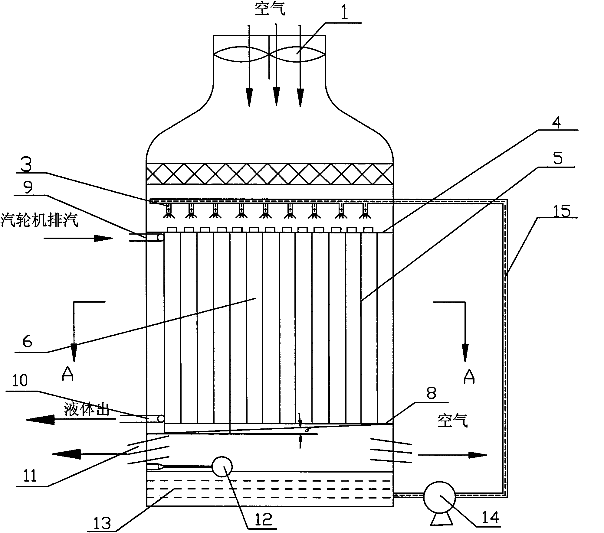
[0031] Attached below figure 1 The parallel flow plate and shell evaporation condensing equipment in the present invention will be described.

[0032] Such as figure 1 As shown, the plate and shell evaporative condensing equipment of the present invention includes an upper box body, a lower box body and a plate and shell heat exchanger 6 in the shape of a rectangular parallelepiped. The top of the upper box is provided with an air inlet. Below the air inlet, a fan 1 and a spray device 3 are arranged in order to realize the air circulation and water distribution of the condensing equipment; the plate and shell heat exchanger 6 is located in the spray device 3 The lower part is connected with the upper box body by bolts or welding; the lower part of the lower box body is lower than the plate and shell heat exchanger 6 with an outlet grid 11, which can make the moist air move out of the lower box body in time, and at the same time in the lower box body The bottom i...

Example Embodiment

[0035] Example 2

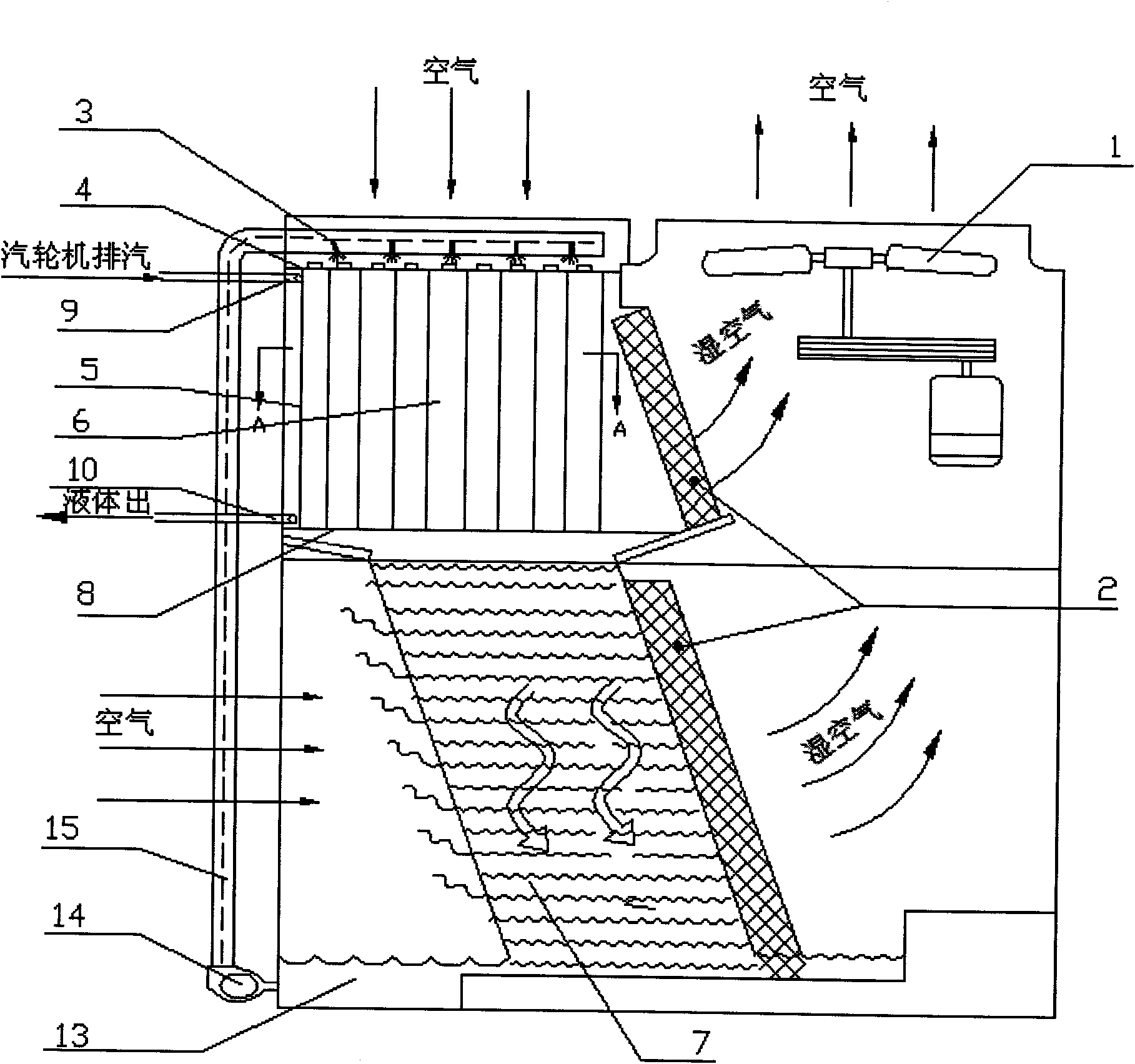
[0036] Such as figure 2 As shown, it is a cross-flow plate and shell evaporative condensing equipment. This embodiment is similar to Embodiment 1, except that the air outlet and the position of the fan 1 are set at the top of the upper box, beside the air inlet, and at the same time A section of PVC packing layer 7 is also provided under the plate and shell heat exchanger 6. When the hot and humid circulating water passes through the packing layer, the contact time between it and the packing layer 7 is prolonged, so as to better reduce the circulating water temperature. The packing layer 7 and the plate and shell heat exchanger 6 are also provided with a water baffle 2 on the side close to the air outlet to guide the spray water flowing out of the plate and shell heat exchanger 6 to the PVC packing.

Example Embodiment

[0037] Example 3

[0038] The manufacturing process of the parallel plate and shell evaporative condensing equipment with plate and shell heat exchanger of the present invention includes the following steps:

[0039] A. First, stamp the stainless steel plate to form transverse and longitudinal grooves and / or flanges, and process one end into a sawtooth structure to obtain a heat exchange plate unit;

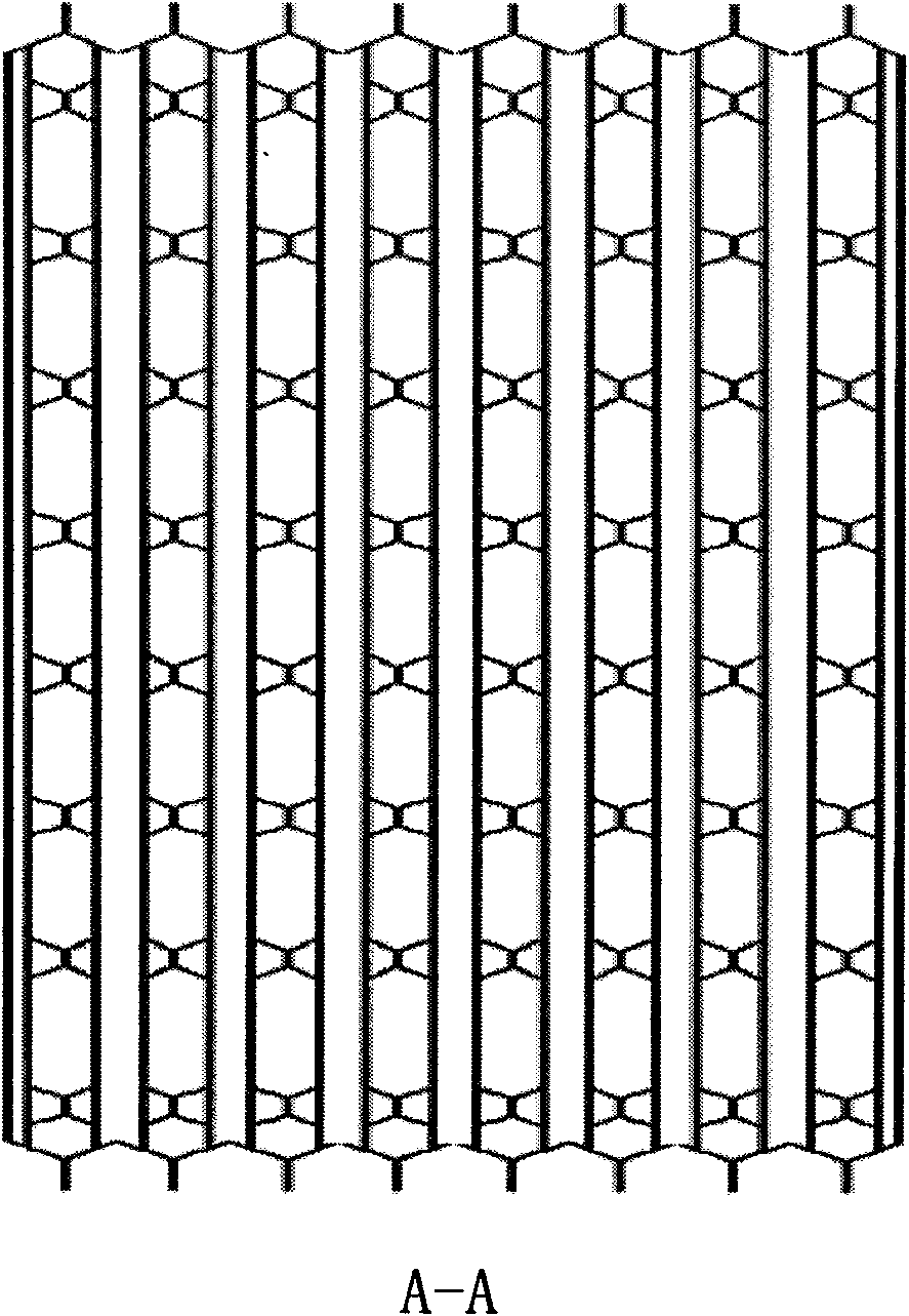
[0040] B. Then take two heat exchange plate units, symmetrically superimpose the heat exchange plate flange to flange, and groove to groove, and weld the adjacent longitudinal and transverse edges of the heat exchange plates into correspondingly Integrated, forming a single heat exchange plate bundle, such as Figure 4 , 5 Shown

[0041] C. Take a plurality of plate and shell heat exchange plate bundles 5, and superimpose the flange of the heat exchange plate bundle on the flange, and the groove on the groove symmetrically. The edges are correspondingly welded into one body;

[0042] D. ...


PUM


Abstract

The invention discloses a lamella heat exchanger comprising a lower pipe plate and heat exchange plate bundles which are vertically welded on the lower pipe plate. The heat exchange pipe bundle arranged on the outmost side is provided with a runner inlet and a runner outlet; each heat exchange pipe bundle comprises at least two mutually-overlapped and welded heat exchange plate sheets; transversely and longitudinally-arranged grooves and/or flanges are evenly distributed on the surfaces of the heat exchange plate sheets; and zigzag structures are arranged at the top ends of the heat exchange plate sheets. The invention simultaneously provides lamella evaporative condensing equipment applying the lamella heat exchanger, comprising an upper box body and a lower box body which are mutually connected as well as a water pump and a circulating water pipeline; an air inlet is formed above the upper box body; a spray device is arranged below the air inlet; and the lamella heat exchanger is positioned below the spray device and fixed to the upper box body through bolts. The invention simultaneously discloses a manufacturing method of the lamella heat exchanger. The lamella heat exchanger and the manufacturing method thereof and the lamella evaporative condensing equipment have high heat exchange efficiency, convenient cleaning, simple processing and low cost.

Description

technical field [0001] The invention relates to the field of refrigeration equipment, in particular to a plate-shell heat exchanger, a manufacturing method thereof, and a plate-shell evaporative condenser. Background technique [0002] Plate and shell evaporative steam condensing equipment is a new type of condensing equipment that combines the advantages of plate and shell heat exchangers and evaporative condensation technology. It is a new type of condensing device designed using unsaturated evaporative cooling technology, breaking through the traditional steam condensation The structural characteristics of the tube or fin heat exchanger in the equipment replace the traditional coil heat exchanger with a new plate and shell heat exchanger, which realizes the integration of condensation and heat dissipation. It has a compact structure, small size, and high pressure resistance. And the heat transfer efficiency is high, so it can be applied in power stations and waste heat po...

Claims


Application Information

Patent Timeline
IPC IPC(8): F28F3/08B23P15/26
Inventor 朱冬生钟振兴
Owner SOUTH CHINA UNIV OF TECH
Why Eureka
Try Eureka