Spent fuel storage rack in pressurized water reactor nuclear power station

A technology for pressurized water reactor nuclear power plant and storage grid, which is applied in the directions of reactor fuel elements, nuclear power generation, reactors, etc. The effect of reducing, ensuring stability, and improving seismic performance

Inactive Publication Date: 2010-07-21
CHINA NUCLEAR POWER ENG CO LTD
View PDF0 Cites 15 Cited by
  • Summary
  • Abstract
  • Description
  • Claims
  • Application Information

AI Technical Summary

Problems solved by technology

[0003]The storage capacity of the traditional spent fuel storage grid is low, which cannot meet the needs of use, and the fixing method of the grid and the pool is also easy to damage the pool under earthquake conditions. Structural damage caused serious accidents

Method used


Image

  • Spent fuel storage rack in pressurized water reactor nuclear power station
  • Spent fuel storage rack in pressurized water reactor nuclear power station
  • Spent fuel storage rack in pressurized water reactor nuclear power station

Examples


Embodiment Construction

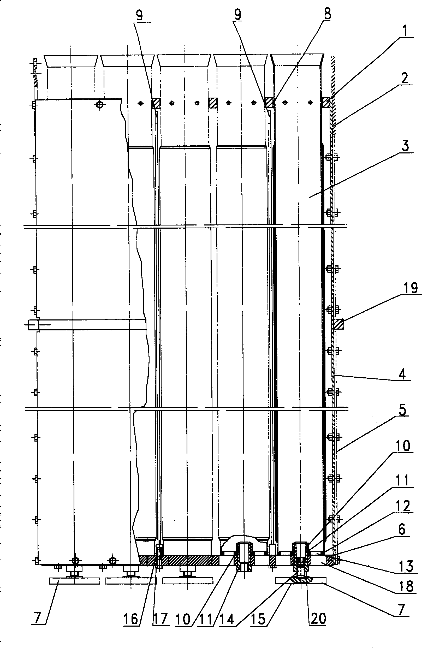
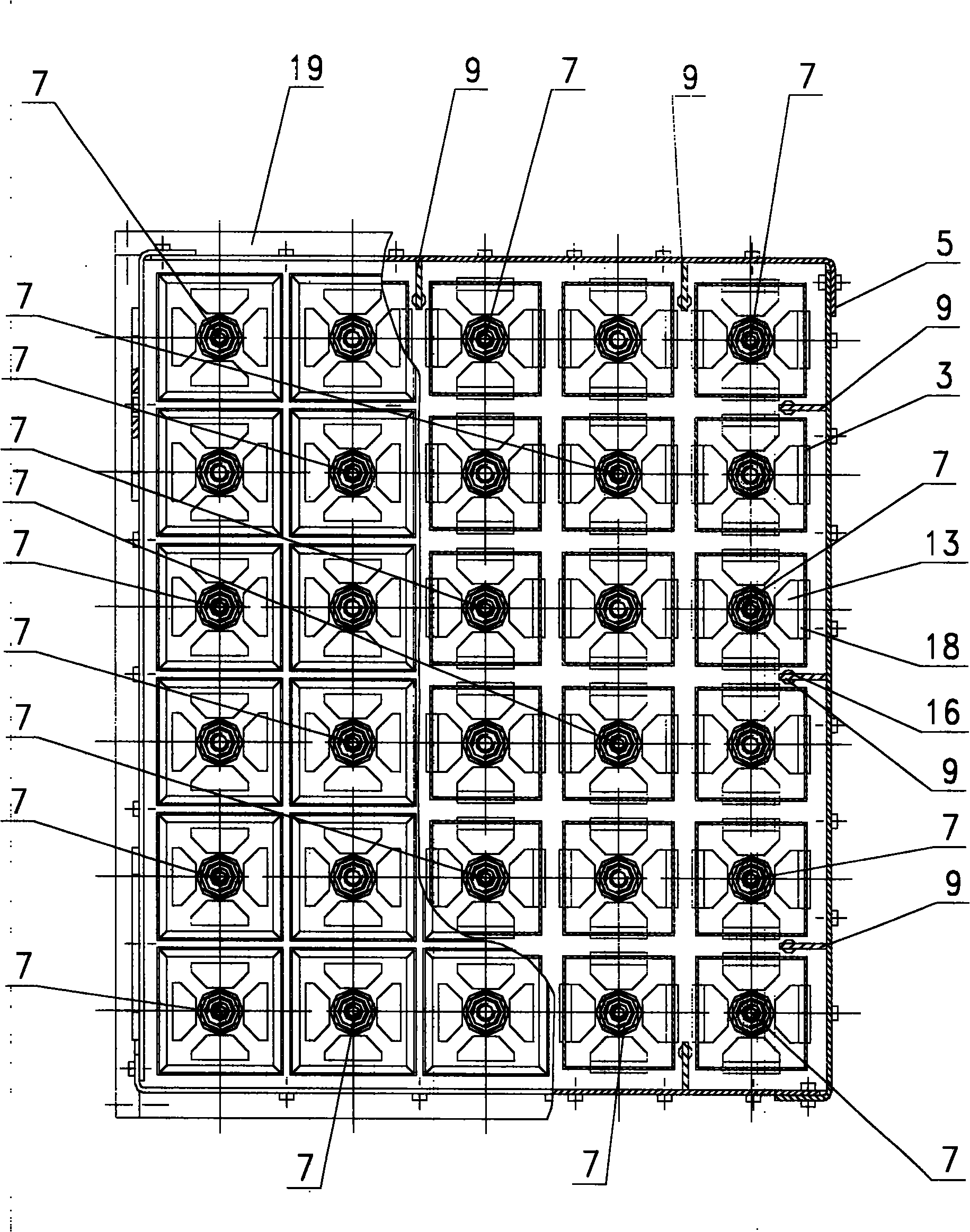
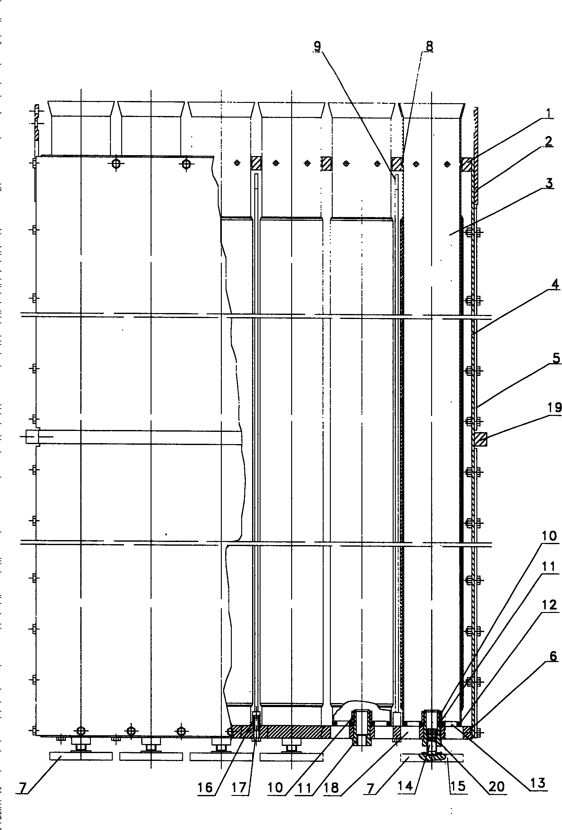
[0015] A storage rack for spent fuel of a pressurized water reactor nuclear power plant provided by the present invention will be further described in detail below in conjunction with the accompanying drawings and embodiments.

[0016] Such as figure 1 with figure 2 As shown, a spent fuel storage grid for a pressurized water reactor nuclear power plant includes two coaming plates 4 and two coaming plates 5, an upper support plate 1 located at the top of the coaming plates 4 and the coaming plates 5, an The lower support plate 6 and the storage sleeve 3 at the bottom of the plate 5, the coaming plate 4 and the coaming plate 5 are plates with right-angled corners, and the corners of the coaming plate 4 and the adjacent coaming plate 5 are fixedly connected by screws. Four coaming plates 4 and 5, upper support plate 1 and lower support plate 6 form a cubic cavity, and the upper support plate 1 and the lower support plate 6 are provided with evenly distributed square holes with ...


PUM


Abstract

The invention relates to a spent fuel storage rack and in particular discloses a spent fuel storage rack in a pressurized water reactor nuclear power station. The storage rack comprises four enclosing plates, an upper bearing plate positioned at the tops of the enclosing plates, and a lower bearing plate and a storage sleeve which are positioned at the bottoms of the enclosing plates, wherein the enclosing plates, the upper bearing plate and the lower bearing plate form a cubic cavity; the storage sleeve is positioned in the square holes on the upper bearing plate and the lower bearing plate; base plates of the storage sleeve are positioned on the lower bearing plate; legs are fixedly connected with the lower bearing plate; thread sleeves on the legs are welded with the lower bearing plate; cylindrical convex plates are arranged at the bottoms of the thread sleeves; the upper ends of the thread sleeves are fastened with the lower bearing plate and the base plates by nuts; adjusting screws are arranged in and in threaded connection with the thread sleeves; the bottoms of the adjusting screws are freely positioned in the spherical recesses of bottom backing plates; and the base plates are provided with through holes communicated with the inside of the storage sleeve and the through holes are communicated with the through holes on the bearing plates. The storage rack has high storage capacity and good shock resistance.

Description

technical field [0001] The invention relates to a spent fuel storage grid, in particular to a nuclear power plant spent fuel storage grid. Background technique [0002] The spent fuel discharged from the reactor during the operation of the nuclear power plant is usually stored in the spent fuel storage pool of the fuel building. Almost all spent fuel assemblies in nuclear power plants are stored underwater in spent fuel storage grids, not only because water can provide operators with a cheap and transparent radiation shielding layer, but also because water can be easily exported out of spent fuel assemblies. decay heat. The early spent fuel storage grids were mainly loose-type spent fuel storage grids. The loose type grid does not contain neutron poison materials. In order to ensure that it meets the requirements of criticality, shielding and thermal engineering, its storage grid pitch is quite large. The storage capacity of the spent fuel storage pool is very limited, and...

Claims


Application Information

Patent Timeline
Patent Type & Authority Applications(China)
IPC IPC(8): G21C19/07
CPCY02E30/30
Inventor 谢亮李建奇唐兴贵吴明王庆
Owner CHINA NUCLEAR POWER ENG CO LTD
Why Eureka
Try Eureka