
Fire emergency lighting power supply having self-checking function

A technology for fire emergency and lighting power supply, applied in the field of power supply, can solve the problems that emergency lighting power supply cannot detect power supply status in real time and find faults, cannot guarantee the normal operation of emergency lighting system, cannot perform automatic alarm or prompt, etc., and achieve intelligent management. , the effect of prolonging the service life and reducing the operating cost

Inactive Publication Date: 2010-07-21
HARBIN INST OF TECH AT WEIHAI
View PDF2 Cites 10 Cited by
  • Summary
  • Abstract
  • Description
  • Claims
  • Application Information

AI Technical Summary

Problems solved by technology

[0003] The purpose of the present invention is to provide a real-time detection of the working state of the power supply for the current existing emergency lighting power supply that cannot detect the power supply state in real time and find faults, and cannot perform automatic alarms or prompts, so that the normal operation of the emergency lighting system cannot be guaranteed. , emergency lighting power supply that detects faults and alarms in time

Method used


Image

  • Fire emergency lighting power supply having self-checking function
  • Fire emergency lighting power supply having self-checking function
  • Fire emergency lighting power supply having self-checking function

Examples


Embodiment Construction

[0032] The specific implementation manners of the present invention will be further described in detail below in conjunction with the accompanying drawings.

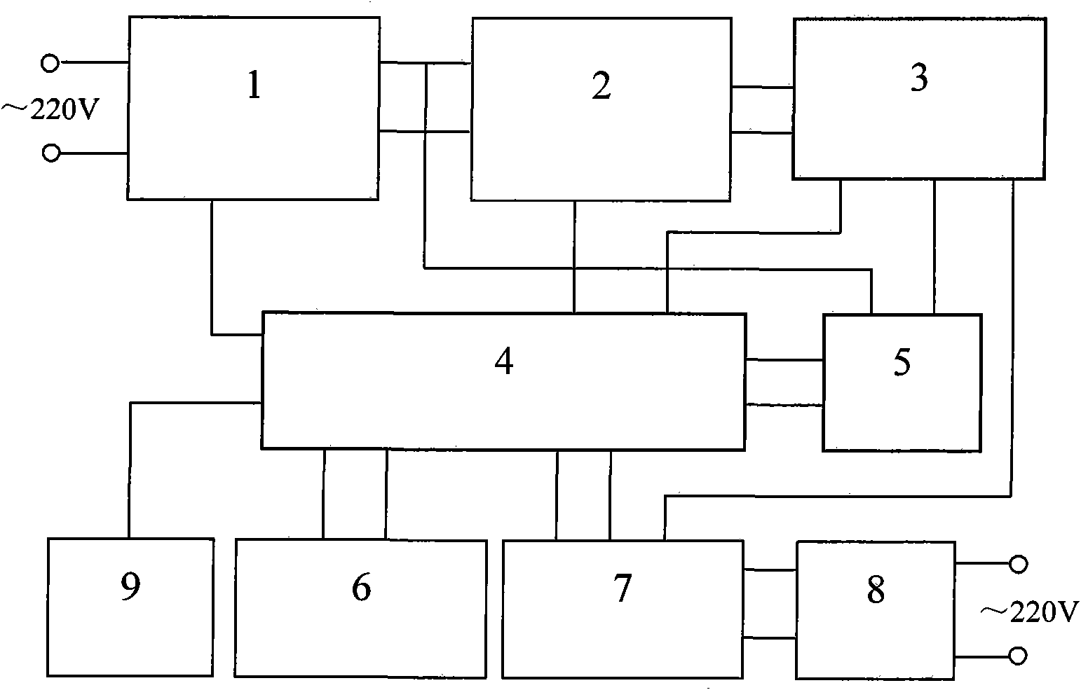
[0033] The composition block diagram of the fire emergency lighting power supply with self-checking function of the present invention is as follows: figure 1 As shown, it mainly includes a microcontroller (4), a switching power supply circuit (1), an inverter circuit (7), a battery charging control circuit (2), a battery pack (3), a microcontroller power supply circuit (5), The keyboard is electrically connected with the indicating circuit (6), and an optional network interface circuit (9) in turn.

[0034] The selection of main devices in the embodiment of the present invention is as follows: the microcontroller adopts P89LPC915FN, the integrated switching power supply controller adopts TOP255YN, the photoelectric coupler adopts TLP521, the voltage comparator adopts LM393, the power MOS transistor adopts STP50N06, and t...


PUM


Abstract

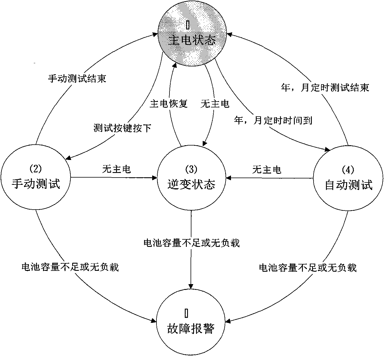
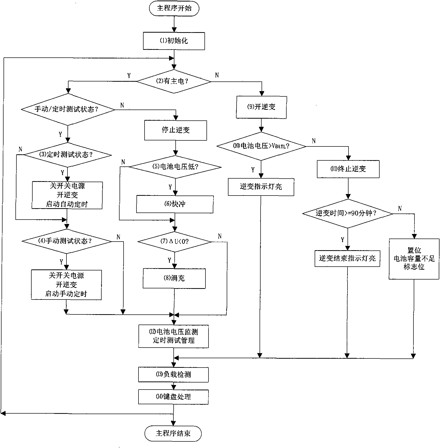
The invention provides a fire emergency lighting power supply having a self-checking function. In the fire emergency lighting power supply, by the combination of a switch power supply and a micro-controller, the digital control of the emergency lighting power supply is realized; by using an digital I / O port of the micro-controller, the working state(main supply and inversion) and the load state of the power supply are checked in real time, and according to the state change, the state conversion is controlled, the state is indicated, and faults are alarmed; the voltage of a battery is sampled by using an A / D converter of the micro-controller, and the corresponding battery charge algorithm and intelligent management of the batter charge are realized by software; and the accurate timing(second, minute, hour, day, month and year) is completed by using a real-time clock of the micro-controller, the automatic timing discharge check of the battery is realized, and the hidden danger caused by the capacity shortage of the battery can be found in time. The fire emergency lighting power supply has the advantages of prolonging the service life of the battery, finding system faults in time, and ensuring the fire emergency lighting power supply to work in the normal state to a maximum degree. The fire emergency lighting power supply having the self-checking function can be widely applied to the fire emergency lighting power supply.

Description

technical field [0001] The invention relates to the field of power supplies, in particular to a fire emergency lighting power supply with a self-check function. Background technique [0002] With the rapid growth of economic scale, the number of large and high-rise public buildings is also increasing rapidly, and the losses caused by building fires and other natural disasters are also increasing. The fire emergency lighting and evacuation indication system can play a role in the first time a disaster occurs, and is crucial to the escape, evacuation and early disaster relief of personnel [1]. At present, a large number of buildings use independent fire emergency lighting and evacuation indication systems with their own power supplies. In this system, the battery life of the power supply is limited, generally two to three years. With the increase of the use time, the capacity of the battery gradually decreases, or even fails. In order to ensure the normal operation of the ba...

Claims


Application Information

Patent Timeline
Patent Type & Authority Applications(China)
IPC IPC(8): H02J9/06H02H3/04
Inventor 孙玉德周凤永马立勇孙丽
Owner HARBIN INST OF TECH AT WEIHAI
Learn More