
Split-type squeeze roller assembly structure and assembly method

A technology of assembling structure and squeezing roller, which is applied in metal processing, grain processing, metal processing equipment and other directions, can solve the problems of shortening the service life of the roller sleeve, frequent replacement cycles, shortening the service life of the squeezing roller, etc., so as to improve the service life. , The effect of shortening the assembly cycle and reducing the cost of spare parts

Inactive Publication Date: 2010-07-28
CITIC HEAVY INDUSTRIES CO LTD +1
View PDF4 Cites 9 Cited by
  • Summary
  • Abstract
  • Description
  • Claims
  • Application Information

AI Technical Summary

Problems solved by technology

[0007] 1) Because the joint surface of the roller shaft and the roller sleeve is an interference connection, the roller sleeve must be heated for a long time before assembly, so that the inner hole of the roller sleeve can obtain a large enough expansion, so that it can be smoothly installed on the roller shaft, wasting a lot of assembly Time, which in turn affects the assembly schedule and increases the cost of production
[0008] 2) Due to the long heating time and high temperature of the roller sleeve, it inevitably has a certain impact on the material of the roller sleeve, which affects the mechanical properties of the roller sleeve, especially the roll surface, and shortens the service life of the roller sleeve
[0009] 3) After the roller sleeve is installed on the roller shaft, the contact surface between the roller sleeve and the roller shaft is relatively large. Due to the uneven cooling of the heated inner hole expansion of the roller sleeve, the outer cooling speed of the roller sleeve is fast, resulting in the middle area of โ€‹โ€‹the joint surface being not 100% complete. Contact, there may even be a gap, the roller sleeve is subjected to high-pressure extrusion during the work of the roller press and the mill, this gap affects the tightness of the roller sleeve and the roller shaft, and reduces the assembly reliability of the roller sleeve and the roller shaft and joint strength, shortening the life of squeeze rolls
[0010] 4) The extrusion roller sleeve is a vulnerable part, and the replacement cycle is relatively frequent
Squeeze rollers assembled by shrink-fitting need special equipment to disassemble, and generally do not have the ability to disassemble on site, so they need to be returned to the factory, which increases maintenance costs and time
[0011] 5) The roller sleeve is assembled by heating. Due to the high temperature of the roller sleeve, it is inconvenient to measure the inner hole. During assembly, the inner hole of the roller sleeve does not fully expand to the size and it will be stuck on the roller shaft. In severe cases, the roller sleeve will be scrapped. Delayed production and increased costs
[0014] 1) The processing of the keyway and key of the roller shaft and the roller sleeve is increased, which increases the production cost and prolongs the production cycle; 2) The stress concentration point is added to the keyway of the roller shaft and the roller sleeve, and the roller press (mill) is normal The extrusion roller is pressed under high pressure during operation, and under the action of cyclic fatigue stress, cracks may even occur at the stress concentration part, which will affect the reliability of the roller shaft and the roller sleeve
3) During long-term load operation, the key is prone to deformation and damage, making it difficult to disassemble and even damage the extrusion roller sleeve and roller shaft

Method used


Image

  • Split-type squeeze roller assembly structure and assembly method
  • Split-type squeeze roller assembly structure and assembly method
  • Split-type squeeze roller assembly structure and assembly method

Examples


Embodiment Construction

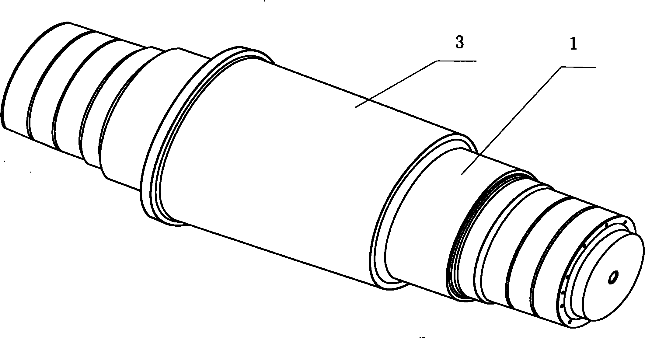
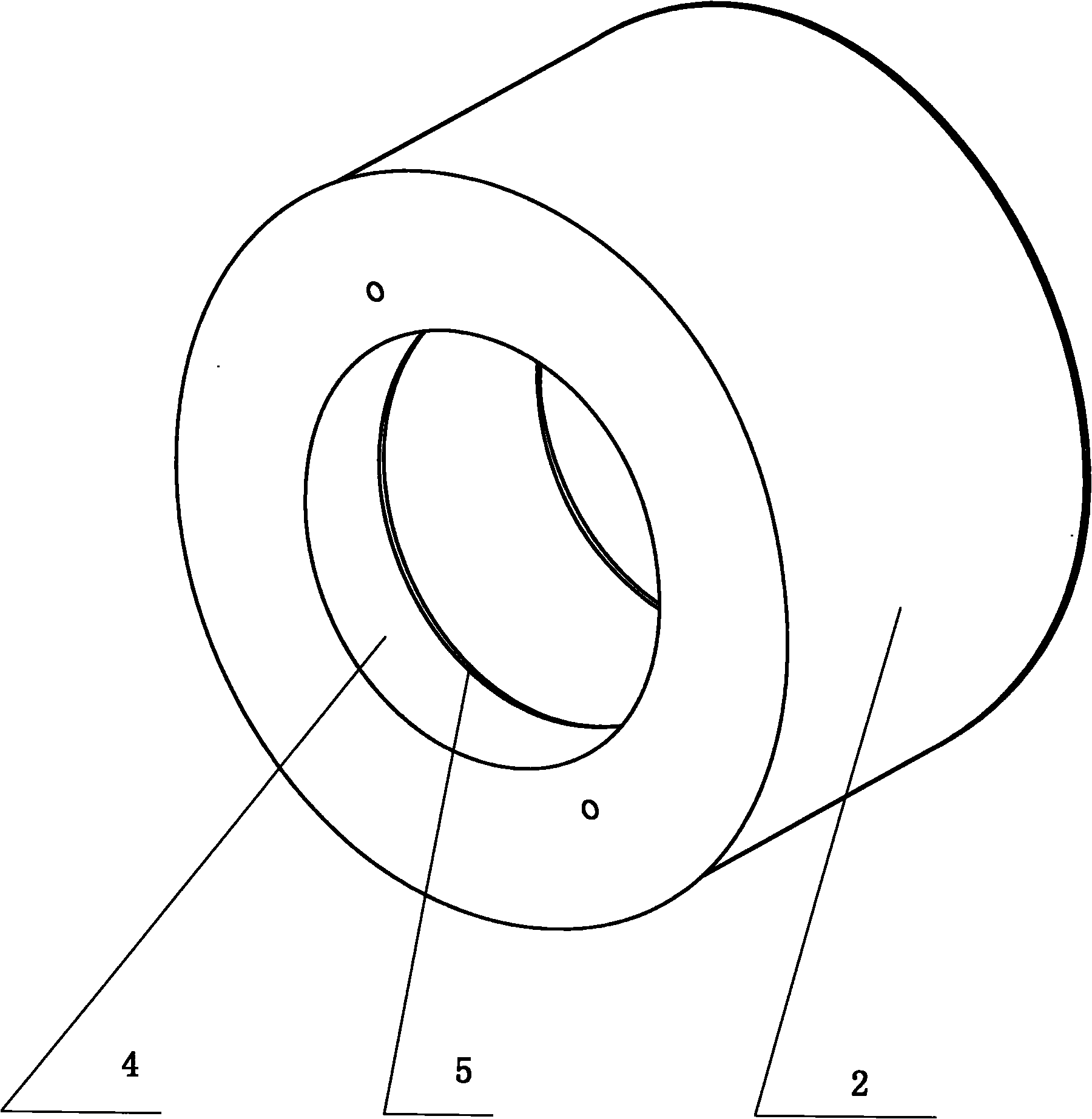
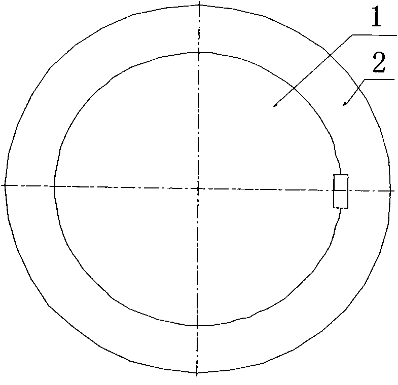
[0034] Such as figure 1 , 2 Shown: a split-type extrusion roller assembly structure and assembly method, the split structure adopts the form of conical surface matching: the matching part of the roller shaft is a conical surface, and the inner hole of the roller sleeve or the matching part of the outer tapered surface of the roller shaft are set to multiple channels Oil groove conical surface. The roller shaft and the roller sleeve are connected by interference fit, and the roller sleeve is assembled by hydraulic pressure. This assembly structure method using high-pressure oil to expand the inner hole of the roller sleeve greatly shortens the assembly cycle of the extrusion roller sleeve, greatly reduces the stress concentration phenomenon caused by the interference connection between the roller shaft and the roll sleeve, and improves the quality of the roll. The service life of the extrusion roller of the press and the grinding product is improved, thereby improving the pr...


PUM


Abstract

The invention discloses a split-type squeeze roller assembly structure and an assembly method. The squeeze roller assembly structure comprises a roll shaft (1) and a roll sleeve (2), wherein matching positions of the outer conical surface (3) of the roll shaft and the inner conical hole (4) of the roll sleeve are in a conical surface shape, the roll shaft (1) and the roll sleeve (2) are in shrink fit connection, and the matching position of the inner conical hole (4) of the roll sleeve is a double-oil groove (5) conical surface. The assembly method of the squeeze roller comprises the following steps: processing the matching surface of the roll shaft and the roll sleeve into the outer conical surface (3), processing the matching surface of the roll sleeve and the roll shaft into the inner conical hole, and processing the matching surface of the inner conical hole (4) of the roll sleeve or the outer conical surface of the roll shaft into a multi-oil groove (5) conical surface, wherein the side of the roll shaft or the roll sleeve is provided with an oil filler point. The invention can shorten assembly period of squeeze roller sleeves, greatly reduce stress concentration caused by shrink fit connection of roll shafts and roll sleeves, prolong life service of squeeze rollers, and improve product performance.

Description

technical field [0001] The invention relates to the technical field of roller press mill equipment, and is especially suitable for a split extrusion roller assembly structure and assembly method of roller press mills in the crushing and grinding operations of brittle minerals in industrial fields such as building materials, metallurgy, mining, coal, and chemical industry. . Background technique [0002] At present, the split squeeze rollers of traditional roller presses (mills) used in the crushing and grinding of brittle minerals in the industrial fields of building materials, metallurgy, mining, coal, chemical industry, etc., the roller shaft and the roller set are equipped with two structural forms: [0003] 1) The roller shaft and the roller sleeve are in pure cylindrical contact. [0004] 2) The joint surface of the roller shaft and the roller sleeve is connected by a key. [0005] The assembly characteristics and disadvantages of these two clock structures are as fol...

Claims


Application Information

Patent Timeline
IPC IPC(8): B02C4/30B23P11/02
Inventor ็Ž‹ไบšๅผบๅผ ๅ…‰ๅฎ‡็Ž‹็ด ็Žฒ็Ž‹็‚ๅˆšๅด”้ƒŽ้ƒŽ
Owner CITIC HEAVY INDUSTRIES CO LTD
Learn More