
Sliding door opening/closing device for vehicle

A technology for opening and closing devices and sliding doors, applied in door devices, vehicle locks, electric locks, etc., can solve the problems such as the lock tongue cannot lock the door, the lock tongue deviates from the top of the lock hole, and the lock tongue deviates from the position above the lock hole. , to achieve the effect of improving operability and safety, simple device structure and easy manufacture

Inactive Publication Date: 2010-07-28
FUJI ELECTRIC CO LTD
View PDF5 Cites 23 Cited by
  • Summary
  • Abstract
  • Description
  • Claims
  • Application Information

AI Technical Summary

Problems solved by technology

However, when the door is closed by a large amount of squishing of the rubber strip on the side of the door, there will be such a problem that the resistance acting on the sliding door will increase, and the bolt will deviate from the position above the lock hole, so that the lock Tongue won't lock the door
[0005] (2) Anti-vibration parts with sound insulation function, wind-proof function and vibration-reduction function are provided, and they are adjacent to the sliding door when the vehicle is running (that is, when the door is closed), and the force acting on the door by these anti-vibration parts exceeds When the value assumed when the door is closed, there will be such a problem that the resistance acting on the sliding door will increase, and the deadbolt will deviate from the position above the lock hole, so that the deadbolt cannot lock the door
The problem, however, is that it is not easy to adjust the resistance from both ends of the intended range while also positioning the deadbolt correctly over the keyhole
[0008] (5) A structure may be adopted in which a gap is provided between the door side rubber strips on the left and right sides to facilitate the adjustment operation to meet the requirements for the door locking action and the prescribed detection accuracy of the door clamping degree Requirements, however, due to the left and right protruding shape of the rubber strips around the door, the gap will be ventilated and noisy, making it difficult to follow this path
The resulting problem is that, with such a large door reaction force, when the handle is operated in an emergency, the outer cable sometimes retracts while the inner cable does not pull relative to the outer cable, so that No emergency unlock

Method used


Image

  • Sliding door opening/closing device for vehicle
  • Sliding door opening/closing device for vehicle
  • Sliding door opening/closing device for vehicle

Examples


Embodiment Construction

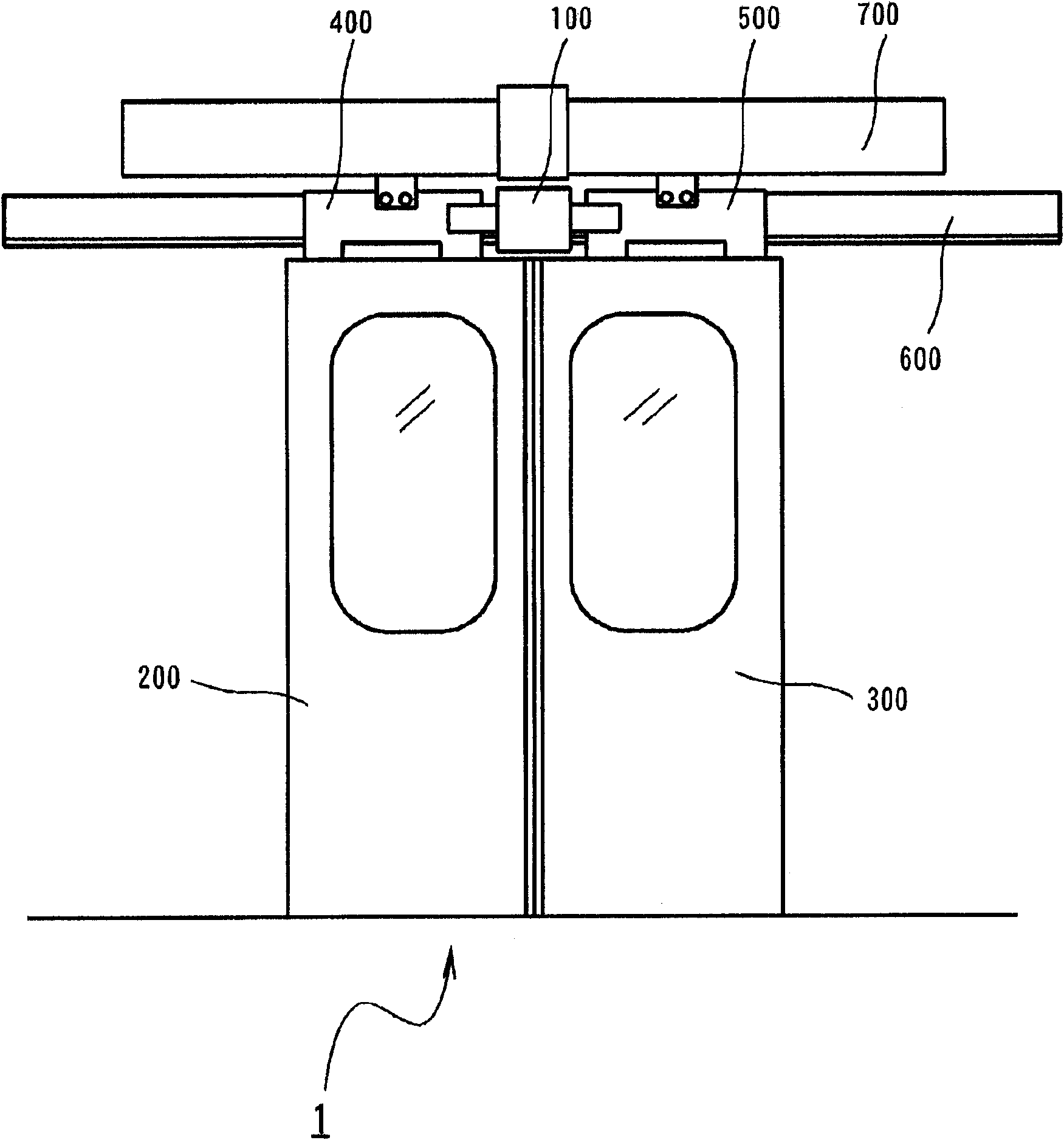
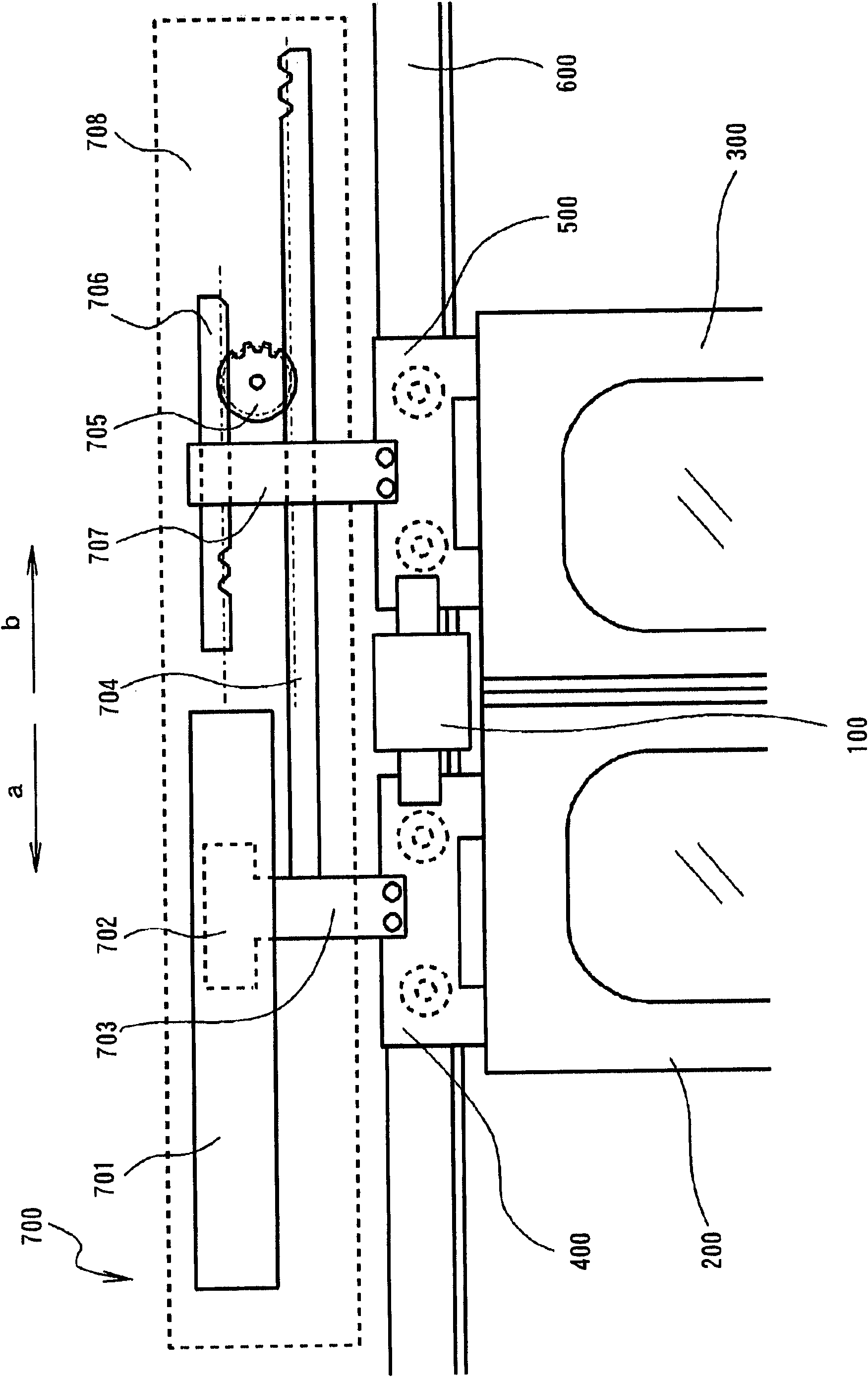
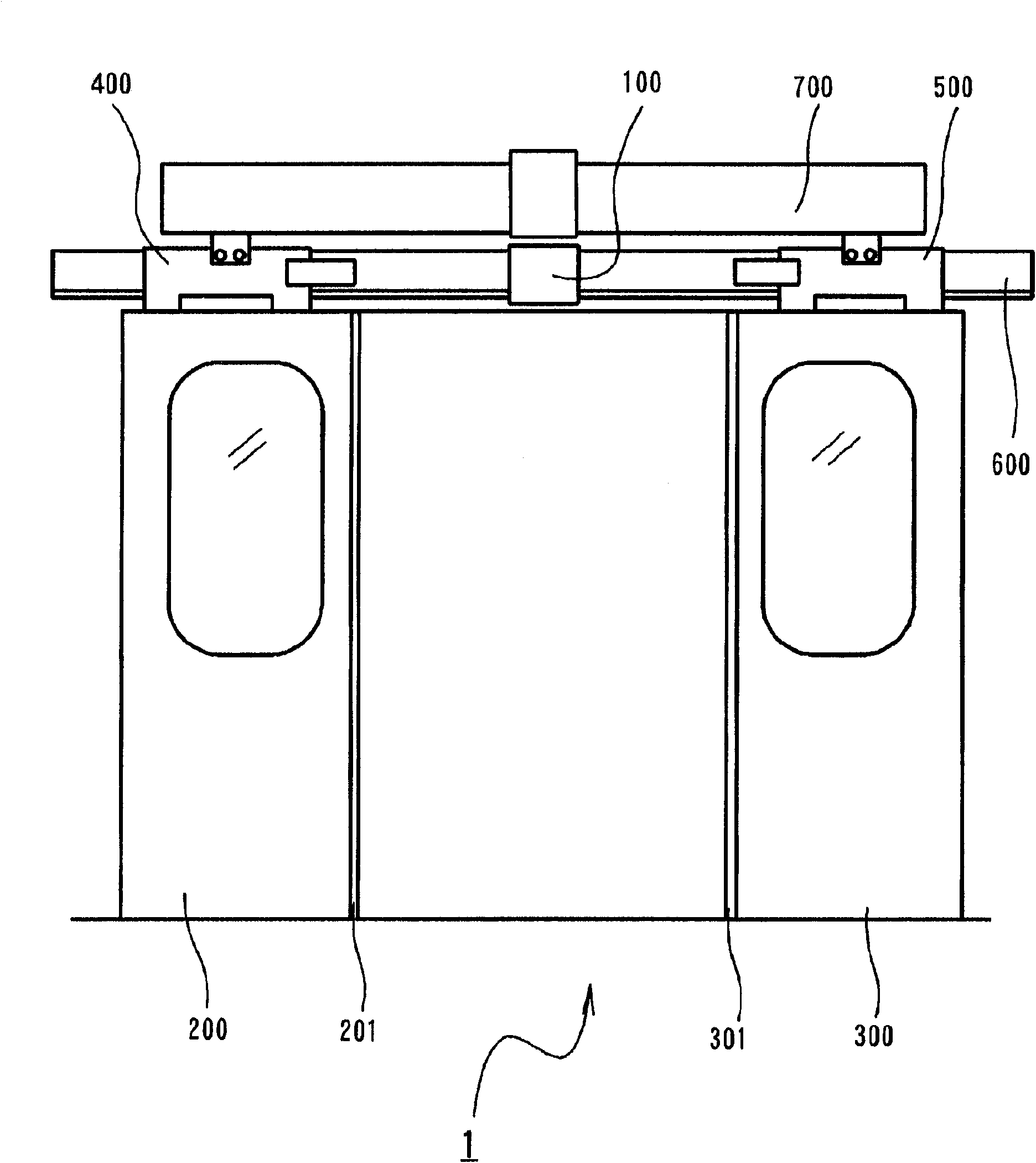
[0051] Several embodiments of the present invention will be described below with reference to the accompanying drawings. First, refer to figure 1 , 2 , 3 and 4 to describe the overall structure of the sliding door opening and closing device 1 for vehicles. Such as figure 1 As shown, the sliding door opening and closing device 1 for a vehicle is provided with at least one lock device 100, a pair of left and right sliding doors 200 and 300, rail moving bodies 400 and 500, sliding door guide rail 600, and an opening and closing drive device 700.

[0052] The lock device 100 has a locking function and can prevent the paired left and right sliding doors 200 and 300 from being opened when the paired left and right sliding doors 200 and 300 have been closed. The lock device 100 generally consists of a magnetic lock device and a bolt lift lock device, which will be described in more detail below.

[0053] The movement of the left and right sliding doors 200 and 300 in opposite di...


PUM


Abstract

The present invention provides a sliding door opening / closing device for a vehicle that applies a sufficient opening / closing drive force to the left and right sliding doors and reduces a force necessary to lock and unlock the latch, despite a simple configuration of the device, and that facilitates the manufacturing process, improves operability and safety, and reduces noise. A lock device, against both sides of which locking portions abut, rotates a columnar permanent magnet so as to form magnetic locking circuits and fixes the locking portions by magnetic forces of the locking magnetic circuits. The rotational operation of the columnar permanent magnet is converted into the downward operation of a latch, and the lowered latch restrains the locking portions with respect to the lock device.

Description

technical field [0001] The present invention relates to a sliding door opening and closing device for a vehicle, which is used for opening and closing the sliding door of the vehicle. Background technique [0002] For example, Japanese Patent Application Laid-Open No. 2000-142392 (JP-A-2000-142392) entitled "Sliding Door Opening / Closing Device for Vehicle" discloses a Related technology of sliding door opening and closing device. A sliding door opening and closing device for a vehicle disclosed in JP-A-2000-142392 is provided with a door lock device capable of correspondingly locking and unlocking the sliding door in response to opening and closing of the sliding door. This door lock device relies on a dead bolt falling into a lock hole to lock the door so that it cannot be opened or closed. This door lock device is configured to raise and lower the deadbolt with a cable device and make it possible to unlock the door by operating a handle by hand. [0003] In conventional...

Claims


Application Information

Patent Timeline
Patent Type & Authority Applications(China)
IPC IPC(8): E05B63/14E05B65/14E05B65/12E05B47/02E05B15/00E05B15/14B61D19/00E05B47/00B61D19/02E05B63/18E05B79/20E05B81/08E05B83/02E05B83/04E05B83/36E05C19/16E05F15/60E05F15/632
CPCB61D19/02B61D19/005E05C19/16E05C2007/007E05B47/026E05B65/0882E05B83/363Y10T292/11
Inventor 稲毛秋夫
Owner FUJI ELECTRIC CO LTD
Learn More