Atkinson cycle engine control system and control method thereof

A control system, Atkinson's technology, applied in engine control, combustion engine, machine/engine, etc., can solve problems such as inability to reduce pumping loss, fuel economy, difficult control of air-fuel ratio, unstable engine combustion, etc., to eliminate Instability of combustion, reduced pumping losses, and the effect of optimizing fuel economy

Inactive Publication Date: 2010-07-28
SHANGHAI JIAO TONG UNIV
View PDF2 Cites 14 Cited by
  • Summary
  • Abstract
  • Description
  • Claims
  • Application Information

AI Technical Summary

Problems solved by technology

[0003] Traditional Atkinson cycle engines mostly adopt the method of large compression ratio or high supercharging, large expansion ratio, late closing of the intake valve or opening the exhaust valve again in the intake compression stroke to achieve the actual expansion ratio greater than the actual compression ratio. To achieve the Atkinsonization of the engine, the existing technology has the following problems: 1. The delayed closing of the intake valve causes the mixed gas to flow back, which leads to the control of the air-fuel ratio that needs to consider the residual fuel in the air passage, and the air-fuel ratio is difficult to control; 2. The load cannot continue to reduce the pumping loss through the delayed closing of the intake valve to improve fuel economy. On the contrary, the engine combustion is unstable, the combustion duration increases, the thermal efficiency deteriorates, and HC emissions increase
However, the invention of this patent opens the exhaust valve during the compression stroke, which will compress a part of the combustible mixture into the exhaust pipe, resulting in waste; in addition, the method of this patent is applied to ordinary non-supercharged engines. Due to the limitation of compression ratio, it works at low very inefficient under load

Method used


Image

  • Atkinson cycle engine control system and control method thereof
  • Atkinson cycle engine control system and control method thereof
  • Atkinson cycle engine control system and control method thereof

Examples


Embodiment Construction

[0030] The embodiments of the present invention are described in detail below in conjunction with the accompanying drawings: this embodiment is implemented on the premise of the technical solution of the present invention, and detailed implementation methods and specific operating procedures are provided, but the protection scope of the present invention is not limited to the following the described embodiment.

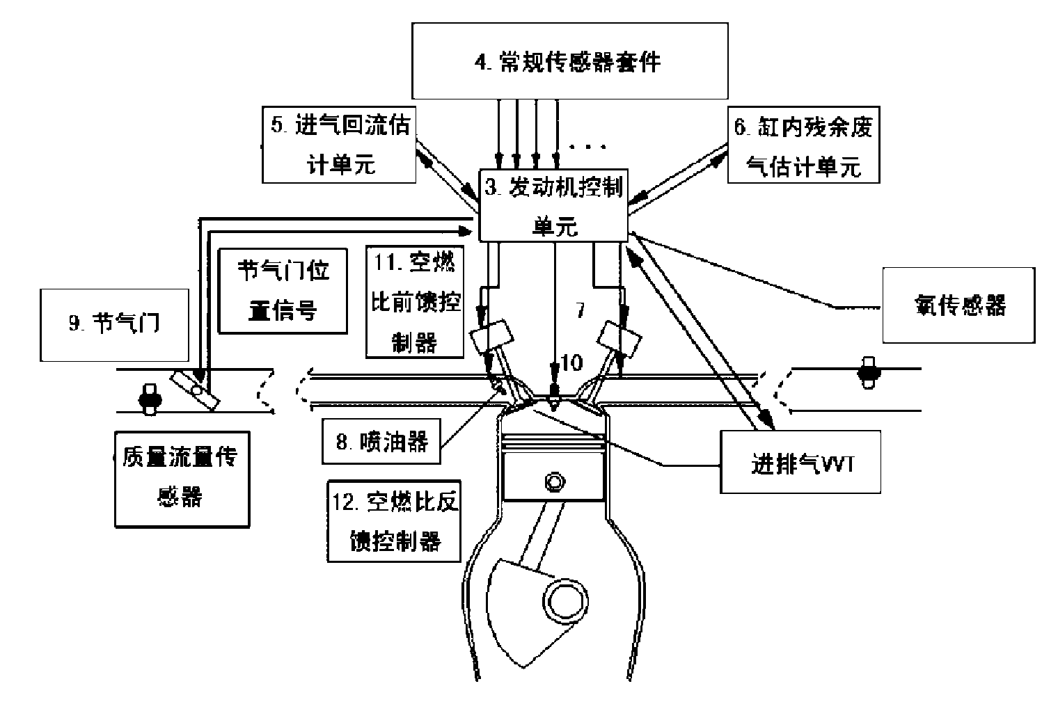
[0031] Such as figure 1 As shown, this example includes: a sensor system 1, a control actuator 2, and an engine control unit 3. The sensor system 1 inputs the collected signal into the engine control unit 3, and the output of the engine control unit 3 includes controlling the throttle valve 9, the fuel injector 8, and the control unit. Change the control commands of the intake and exhaust timing devices and the spark plug 10 to the control actuator 2.

[0032]The sensor system 1 includes: a conventional sensor set 4, an intake air return estimating unit 5 and an in-c...


PUM


Abstract

The invention relates to an Atkinson cycle engine control system belonging to the technical field of automobile engines and comprising a sensor system, a control executing mechanism and an engine control unit, wherein the sensor system is used for inputting the collected signals to the engine control unit, and the engine control unit is used for outputting a control instruction comprising a control throttle valve, an oil atomizer, a variable air inflow and exhaust correct timing device and a spark plug to the control executing mechanism. The invention can accurately control the air-fuel ratioof an Atkinson cycle engine and improve the economy and the exhaustion of the Atkinson cycle engine, adopts greatly higher geometrical compression ratio than that of the general gasoline engine so the opening of an intake valve is enlarged under low load, controls the oil atomizing amount and the ignition advance angle and controls the air-fuel ratio in the range of 16-19 so that thin combustion is formed, and therefore, the Atkinson cycle engine has improved combustion efficiency and more stable combustion.

Description

technical field [0001] The invention relates to a system and a control method in the technical field of automobile engines, in particular to an Atkinson cycle engine control system and a control method thereof. Background technique [0002] The concept of the Atkinson cycle engine was proposed early in the 1880s. In the Atkinson cycle, the actual expansion ratio is greater than the actual compression ratio, the proportion of heat energy converted into mechanical energy is large, and the power stroke is long; the effective displacement of the engine is adjusted according to the load of the engine by using the closing timing of the intake valve, and the throttle valve is fully opened or Wide open greatly reduces engine pumping losses at part load and improves fuel economy. However, although the Atkinson cycle engine has the characteristics of high thermal efficiency, it has the problem of low power. Therefore, in the era of pursuing power in the past, the research of Atkinso...

Claims


Application Information

Patent Timeline
Patent Type & Authority Applications(China)
IPC IPC(8): F02D41/14
CPCY02T10/142Y02T10/12
Inventor 许敏赵金星王斌杨杰刘双寨
Owner SHANGHAI JIAO TONG UNIV
Why Eureka
Try Eureka