Multifrequency patch antenna device

A patch antenna, patch technology, applied in the antenna grounding device, antenna support/installation device, antenna and other directions, can solve the problems of insufficient gain, poor stability, low precision, etc., to achieve simple matching, good consistency, measurement The effect of precision assurance

Active Publication Date: 2010-07-28
HARXON CORP
View PDF1 Cites 28 Cited by
  • Summary
  • Abstract
  • Description
  • Claims
  • Application Information

AI Technical Summary

Problems solved by technology

[0008] The main purpose of the present invention is to provide a high-precision, high-stability, high-gain multi-frequency patch antenna device, in order to overcome the shortcomings of low precision, poor stability and insufficient gain in the prior art

Method used


Image

  • Multifrequency patch antenna device
  • Multifrequency patch antenna device
  • Multifrequency patch antenna device

Examples


Embodiment Construction

[0028] The device of the present invention will be further described in detail below in conjunction with the accompanying drawings and specific embodiments.

[0029] The multi-frequency patch antenna device of the present invention has a very wide range of applications in satellite positioning systems and mobile communication systems, especially in high-end fields with high precision and zero phase center requirements, and has very important value. The device of the present invention can effectively exert its performance advantages on equipment including GPS receiver antennas, GPS+GLONASS receiving antennas and base station antennas.

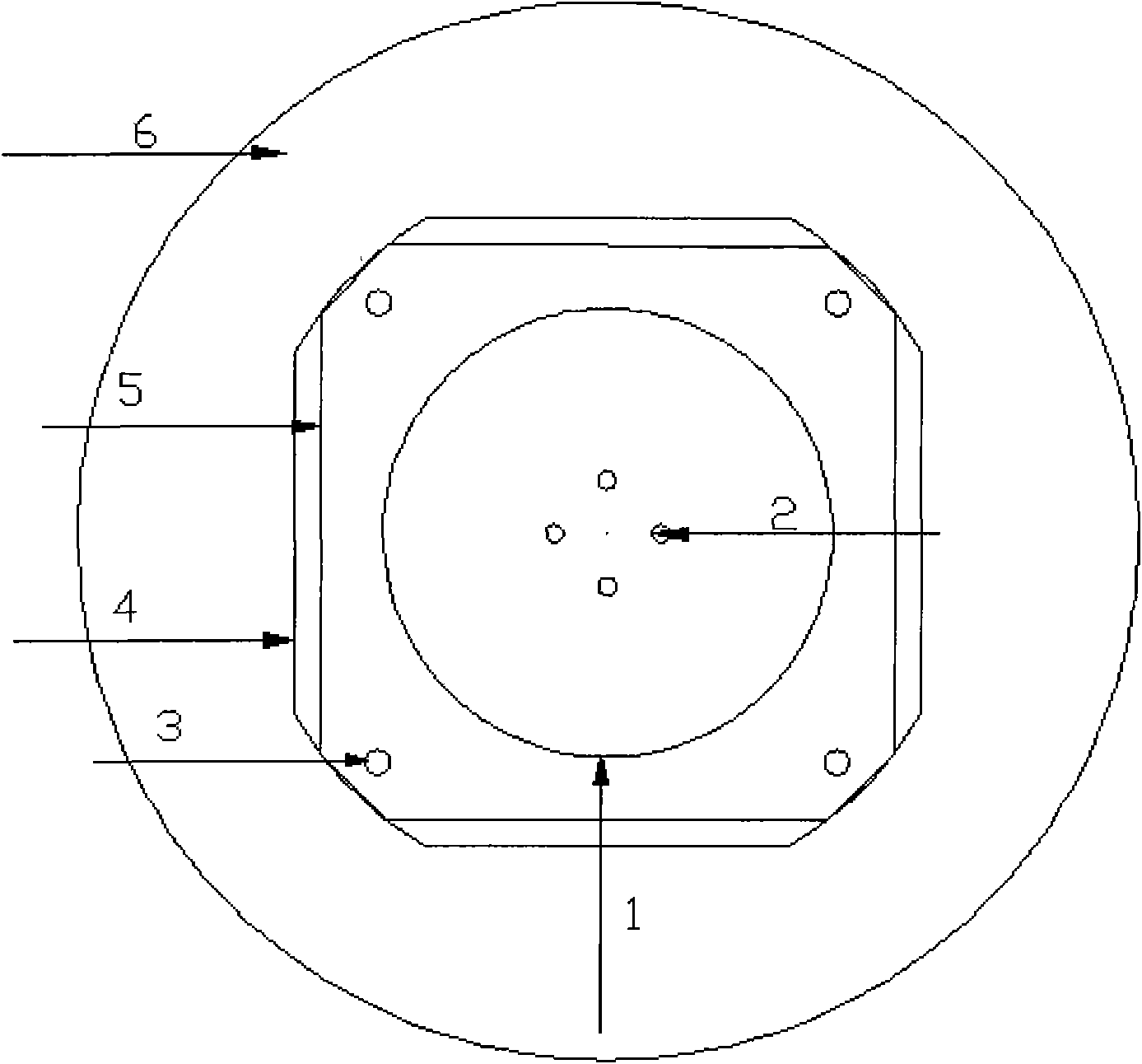
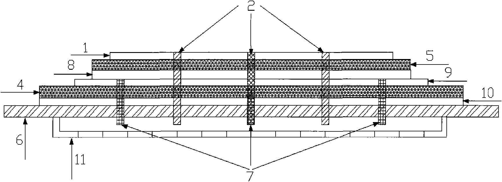
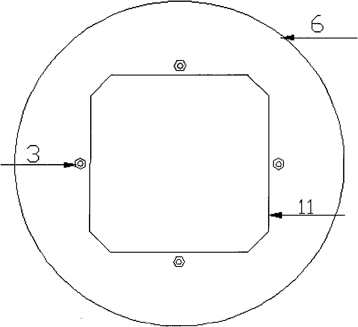
[0030] Figure 1 to Figure 7 It is a structural diagram of a specific embodiment of the multi-frequency patch antenna device of the present invention.

[0031] Such as figure 1 with figure 2 As shown, the multi-frequency patch antenna device includes an upper patch 1, four sets of locking screws 3, an upper high-frequency substrate 5, a seco...


PUM


Abstract

The invention relates to a multifrequency patch antenna device, comprising a patch antenna, a printed circuit board (PCB), a shielding case and a low-noise amplifying circuit, wherein the patch antenna further consists of a patch antenna, a multi-frequency band feed network, a multi-frequency band feed probe and at least four feedback points; the at least four feedback points form at least two groups of feed points; one end of each of the at least two feed points is connected with the patch antenna, and the other end thereof respectively passes through the PCB via the multi-frequency band feed probe to be connected with the multi-frequency band feed network; and a shielding case is connected with the PCB. The invention improves the stability of antenna phase center, lowers axial ratio, and enables the matching to be much simpler and the antenna to become more compact. The device in the invention can receive multipath carrier at the same time, thus eliminating interference on an ionized layer and improving measurement precision.

Description

technical field [0001] The invention relates to the field of communication antennas, in particular to a multi-frequency patch antenna device in a measuring antenna. Background technique [0002] With the continuous development of satellite navigation and measurement technology, satellite positioning system has also been widely used. At present, many countries around the world have established their own satellite positioning systems, such as the Beidou system in China, the GPS system in the United States, the GLONASS system in Russia, and the GALILEO system in Europe. With the continuous maturity of these satellite systems and the deepening of the civilian application process, the high-performance receiving equipment measurement antenna, which is one of the key technologies of the satellite positioning system, has become a hot technology that has attracted much attention. [0003] In addition, the development of mobile communication systems has also brought about changes in ...

Claims


Application Information

Patent Timeline
Patent Type & Authority Applications(China)
IPC IPC(8): H01Q1/12H01Q1/48H01Q5/01H01Q23/00H01Q5/10
CPCH01Q9/0414
Inventor 贾延波
Owner HARXON CORP
Why Eureka
Try Eureka