Engine residual heat power generation device and power generation module thereof

A waste heat power generation and engine technology, applied in the direction of generators/motors, electrical components, etc., can solve problems such as large temperature difference, exceeding the optimal temperature range, and insufficient exhaust heat, so as to improve utilization rate, improve thermoelectric conversion efficiency, reduce The effect of temperature difference

Inactive Publication Date: 2010-07-28
NINGBO INST OF TECH ZHEJIANG UNIV ZHEJIANG
View PDF3 Cites 17 Cited by
  • Summary
  • Abstract
  • Description
  • Claims
  • Application Information

AI Technical Summary

Problems solved by technology

Using the waste heat power generation method of this invention patent, when the engine is running at high speed, the heat provided to the thermoelectric converter will be too much, and the temperature difference between the high temperature end and the low temperature end of the thermoelectric convert

Method used


Image

  • Engine residual heat power generation device and power generation module thereof
  • Engine residual heat power generation device and power generation module thereof
  • Engine residual heat power generation device and power generation module thereof

Examples


Embodiment Construction

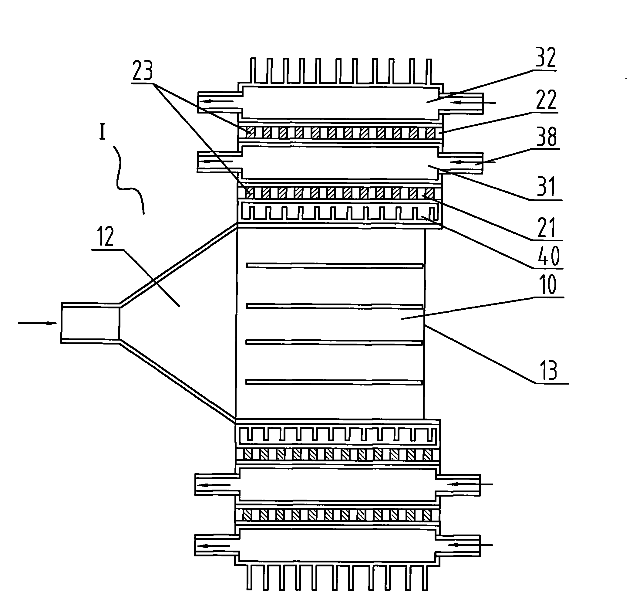
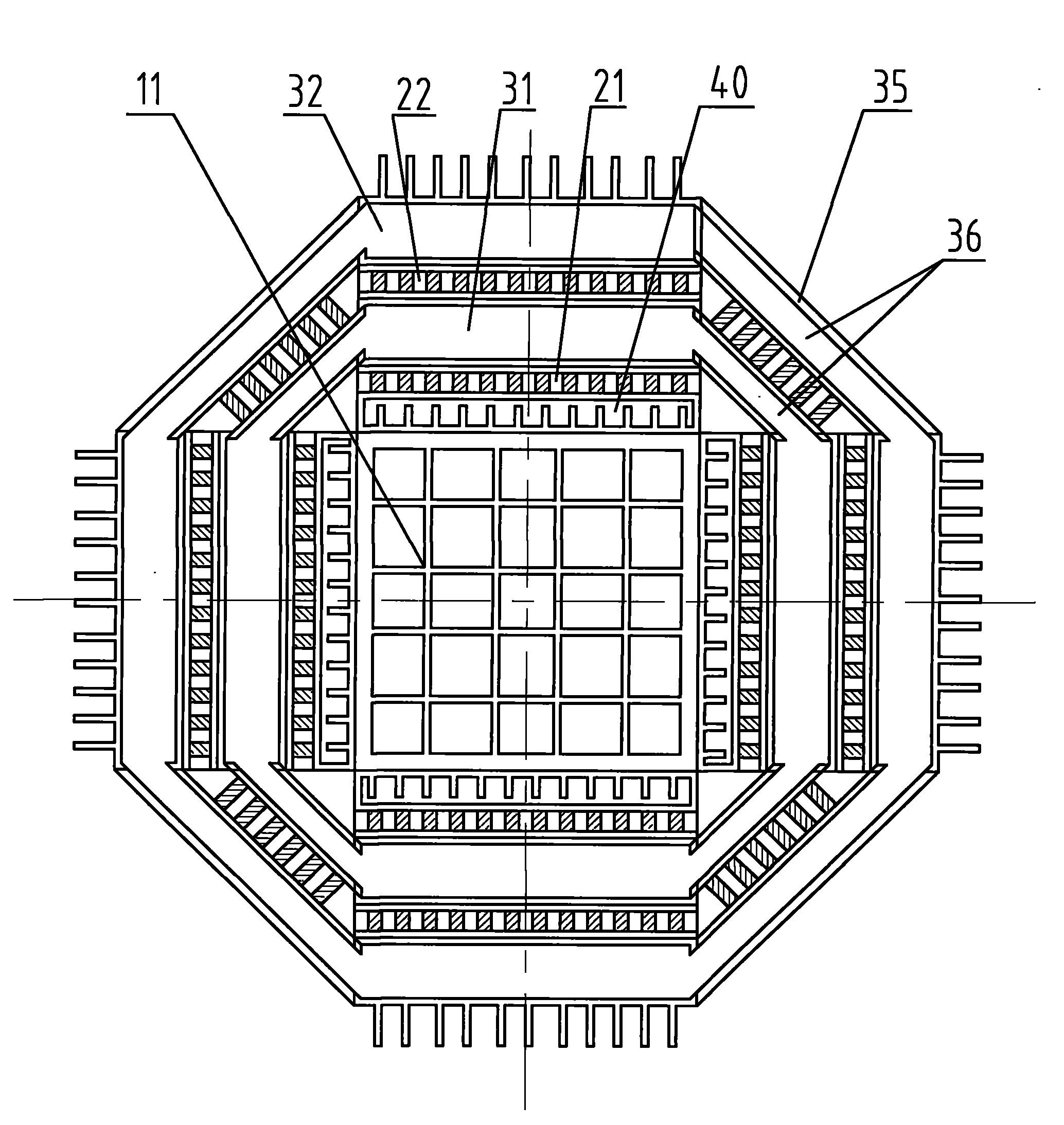
[0024] Refer to the attached Figure 1 to Figure 5 . The engine waste heat power generation module 1 of this embodiment includes a gas pipeline 10, a thermoelectric converter layer, and a cooler layer, wherein the thermoelectric converter layer includes a first thermoelectric converter layer 21 and a second thermoelectric converter layer 22, and the cooler The layers include a first cooler layer 31 and a second cooler layer 32, and an energy storage layer 40 is also provided between the gas pipes and the first thermoelectric converter layer. The first thermoelectric converter layer 21 is located between the energy storage layer and the first cooler layer 31 , and the second thermoelectric converter layer is located between the first cooler layer 31 and the second cooler layer 32 .

[0025] In order to increase the heat-absorbing area of ​​the gas pipe wall, a grid 11 such as a grid or a rib plate can be arranged in the gas pipe 10 . The grids 11 are distributed along the dire...


PUM


Abstract

The invention discloses an engine residual heat power generation module which comprises a gas pipeline, a thermoelectric converter layer and a cooler layer, wherein an energy storage device layer is further arranged between the gas pipeline and the thermoelectric converter layer. The invention simultaneously discloses an engine residual heat power generation device, which at least comprises two stages of the engine residual heat power generation modules; and the gas pipelines, the thermoelectric converter layers and the cooler layers of the adjacent two stages of the engine residual heat power generation modules are communicated. The engine residual heat power generation module can absorb residual heat of exhaust gas and produce the temperature difference in the engine residual heat power generation module, and a thermoelectric converter can utilize the temperature difference for completing the power generation function. The use of the engine residual heat power generation module can improve the thermoelectric conversion efficiency of the thermoelectric converter, the use is convenient and the manufacture is simple.

Description

technical field [0001] The invention belongs to the technical field of reuse of engine waste heat, and particularly relates to an engine waste heat power generation device and a power generation module thereof. Background technique [0002] With the rising price of non-renewable petroleum energy and the continuous expansion of environmental pollution, environmental protection and energy saving have become the themes of today's social development. Investigations and studies have shown that only part of the energy emitted by the combustion of engine fuel is effectively utilized. The energy utilization rate of diesel engines is generally 34% to 38%, and the energy utilization rate of gasoline engines is generally 25% to 28%. Other energy is discharged to the engine. Outside the body, the heat taken away by the exhaust gas alone accounts for 30% to 45% of the heat generated by the fuel in the engine, while the heat taken away by the engine circulating cooling water accounts for ...

Claims


Application Information

Patent Timeline
IPC IPC(8): H02N11/00
Inventor 宋瑞银王贤成张美琴
Owner NINGBO INST OF TECH ZHEJIANG UNIV ZHEJIANG
Why Eureka
Try Eureka