High-precision hydraulic servo control system

A hydraulic servo and control system technology, applied to fluid pressure actuation system components, fluid pressure actuation devices, mechanical equipment, etc., can solve problems such as unsatisfactory stability, low control efficiency, and unreachable control accuracy, and achieve Increased speed, improved positioning accuracy, and low overall cost

Active Publication Date: 2010-08-04
NINGBO ANXIN CNC TECH
View PDF7 Cites 22 Cited by
  • Summary
  • Abstract
  • Description
  • Claims
  • Application Information

AI Technical Summary

Problems solved by technology

Since this hydraulic servo control system still uses a single servo motor, it still has the above-mentioned shortcomings of low control efficiency, unsatisfactory stability, and control accuracy that cannot meet higher requirements.

Method used


Image

  • High-precision hydraulic servo control system
  • High-precision hydraulic servo control system
  • High-precision hydraulic servo control system

Examples


Embodiment Construction

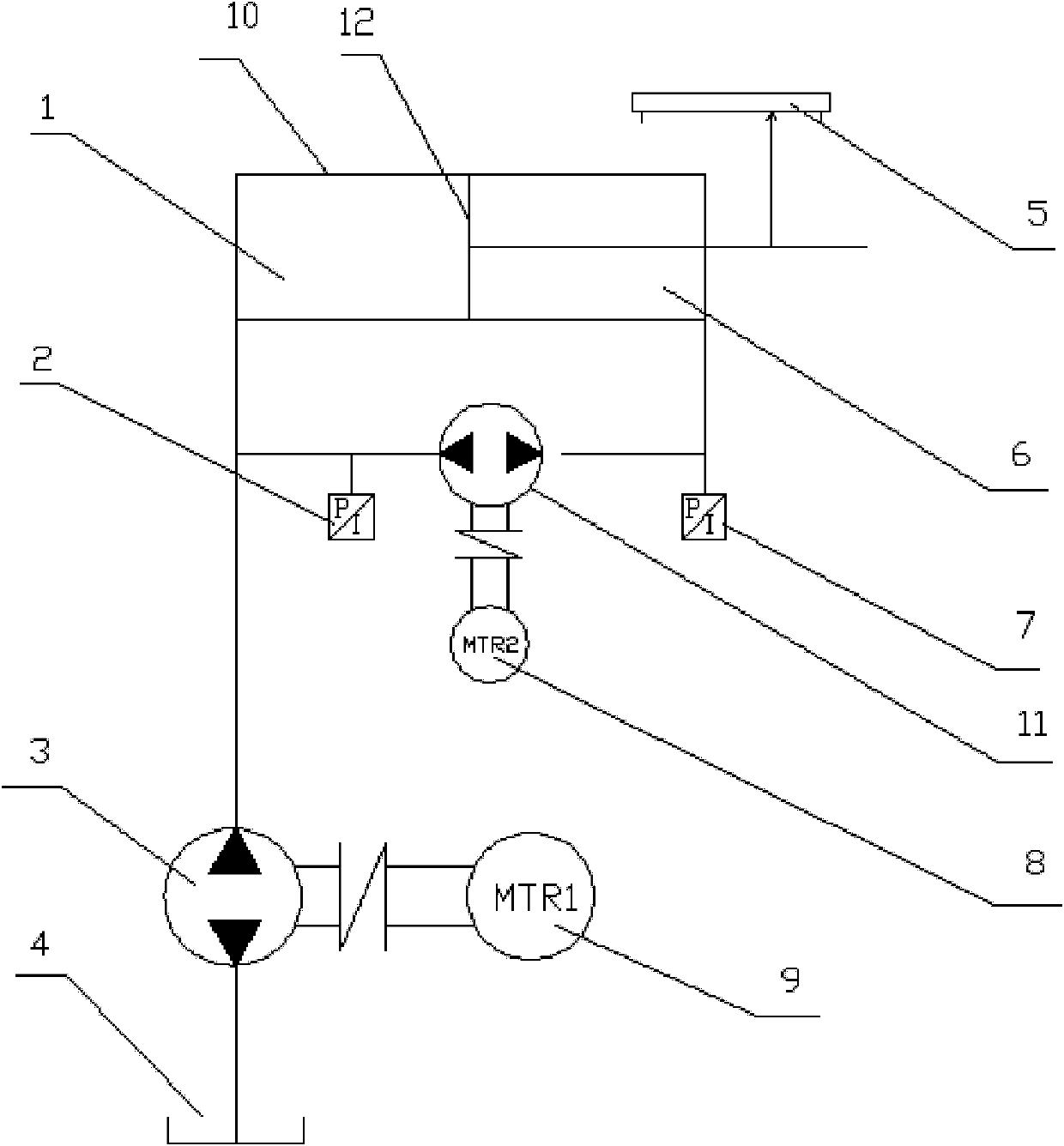
[0017] The present invention will be further described in detail below in conjunction with the accompanying drawings and embodiments.

[0018] Such as figure 1 As shown, the piston 12 of the hydraulic cylinder 10 is fixedly connected with the sliding block of the position sensor 5 . The position sensor feeds back the position of the oil cylinder piston 12 to the control computer in real time. The pressure sensor 2 communicates with the rodless chamber of the hydraulic cylinder 10, and feeds back the pressure signal of the rodless chamber to the control computer. The pressure sensor 7 communicates with the rod chamber of the hydraulic cylinder 10, and feeds back the pressure signal of the rod chamber to the control computer. The main motor 9 is connected with the hydraulic pump 3, and the hydraulic pump 3 can absorb oil from the oil tank 4 through forward and reverse rotation, and output hydraulic oil with a certain pressure and flow rate to the oil cylinder 10, and can also ...


PUM


Abstract

The invention relates to a high-precision hydraulic servo control system which comprises a control computer, an oil cylinder, a position sensor, pressure sensors, a driving servo motor with a hydraulic pump, a driven servo motor with a hydraulic pump, a driving servo driver and a driven servo driver. A control system for controlling the motors comprises pressure sensors, the servo drivers and the control computer, the servo drivers and the control computer are connected with the motors, the oil cylinder is connected with the position sensor for detecting the actual position of the oil cylinder, and a rod cavity and a rodless cavity of the oil cylinder are respectively provided with the pressure sensors for detecting and feeding back the oil pressure of an oil outlet and an oil inlet to the control computer which controls the rotating speed and the torque of the driving motor and controls pressure and flow needed by an oil pump output system by calculating and processing a pressure signal fed back from the rodless cavity. The control computer calculates and processes a pressure signal fed back from the rod cavity and outputs a control signal to the servo drivers to control the output pressure and the output flow of the oil pump by controlling the rotating speed and the torque of the driven motor. Oil is sucked from the oil outlet into the driven motor when the oil cylinder in an accelerating process, and the pressure of the oil outlet is backed when the oil cylinder in a decelerating process.

Description

technical field [0001] The invention relates to a hydraulic control system and a control method, in particular to a high-precision hydraulic servo control system and a control method. Background technique [0002] The hydraulic system uses the motor to provide the power base, uses the hydraulic pump to convert the mechanical energy into pressure, pushes the hydraulic oil, and changes the flow direction of the hydraulic oil by controlling various valves, thereby pushing the hydraulic cylinder to make actions in different strokes and directions to complete various equipment. Different action needs, so in order to achieve smooth operation, a better control system is required. [0003] Various existing hydraulic servo control systems usually use a single servo motor as the power source, and the control computer controls the speed and torque of the servo motor according to the pressure signal fed back from the oil inlet of the cylinder, so that the hydraulic pump outputs a certai...

Claims


Application Information

Patent Timeline
Patent Type & Authority Applications(China)
IPC IPC(8): F15B21/08
Inventor 李大寅谢子方
Owner NINGBO ANXIN CNC TECH
Why Eureka
Try Eureka