Testing device suitable for measuring constant-pressure specific heat capacity of flow fluid

A technology of constant pressure specific heat capacity and experimental device, applied in the field of constant pressure specific heat capacity, can solve the problems of long residence time, large heat loss of flow heat transfer and radiation heat loss, lack of experimental data of constant pressure specific heat capacity of aviation kerosene, etc. Improve and reduce the effect of convective heat transfer heat loss and radiation heat loss

Inactive Publication Date: 2010-08-04
BEIHANG UNIV
View PDF0 Cites 22 Cited by
  • Summary
  • Abstract
  • Description
  • Claims
  • Application Information

AI Technical Summary

Problems solved by technology

However, under supercritical pressure, aviation kerosene will have different thermophysical properties from those under normal pressure, and the composition of various oil products will be different. The lack of constant pressure specific heat capacity experimental data of aviation kerosene RP-3 at home and abroad is not conducive to this new type of oil. Research and application of cooling methods
Some research institutions at home and abroad use static experimental equipment to measure the specific heat capacity of the fluid at constant pressure, but under static conditions, a certain quality of kerosene stays in the test equipment for a long time, and the measurement results include the absorption of kerosene components due to chemical changes ( or the heat released), it is impossible to better simulate the real flow state of aviation kerosene in the short residence time of the engine
At the same time, under high temperature conditions, the longer residence time of aviation kerosene will cause irreversible changes in the composition of kerosene, which will affect the measurement results of "downstream" test points
During the measurement process, the convective heat transfer heat loss and radiation heat loss are relatively large, and there is a large error in the measurement data

Method used


Image

  • Testing device suitable for measuring constant-pressure specific heat capacity of flow fluid
  • Testing device suitable for measuring constant-pressure specific heat capacity of flow fluid
  • Testing device suitable for measuring constant-pressure specific heat capacity of flow fluid

Examples


Embodiment Construction

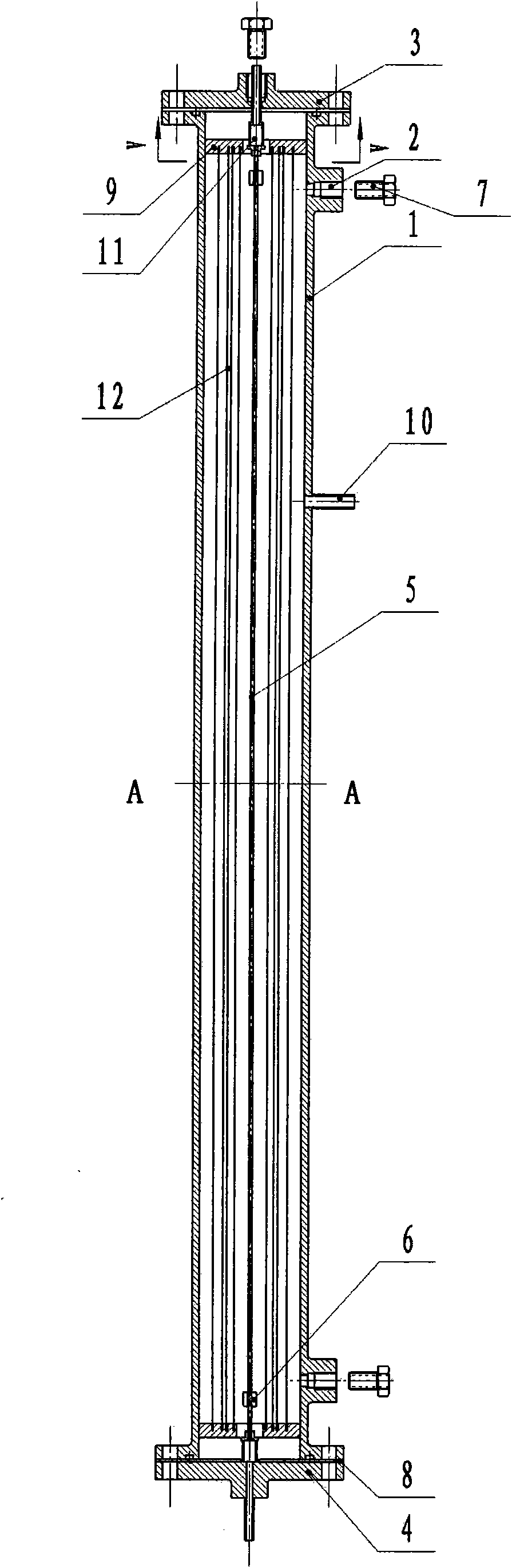
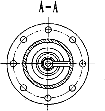
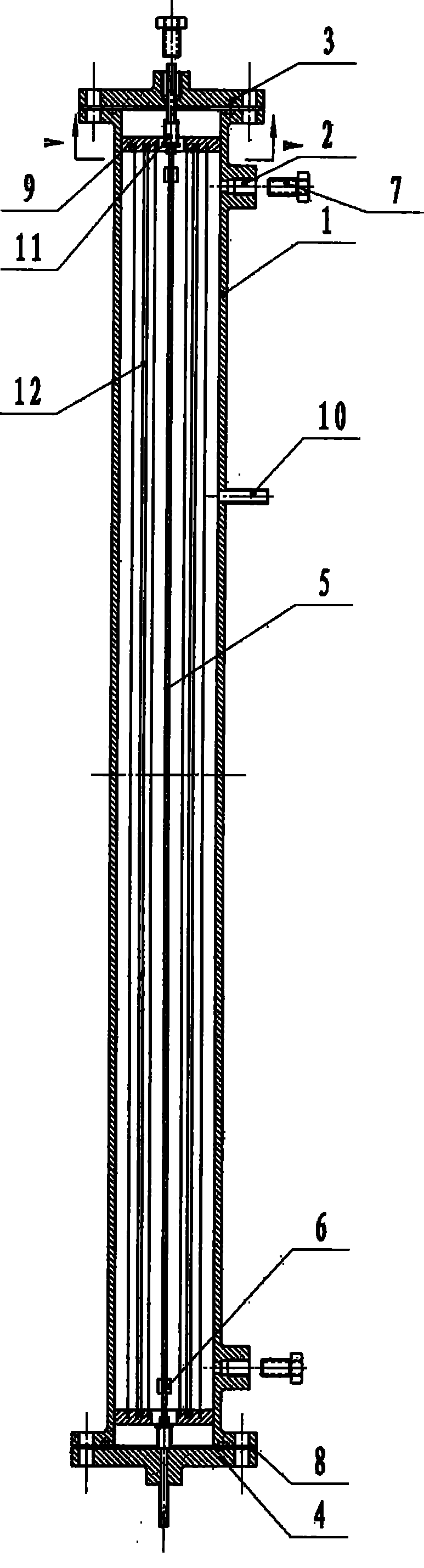
[0012] The present invention will be further described in detail below in conjunction with the accompanying drawings. see figure 1 shown. The experimental equipment includes a vacuum chamber, a heating part and a measuring part. The vacuum chamber includes a vacuum chamber shell (1), a low-temperature flange (3), and a high-temperature flange (4). The heating part includes an experimental heating tube (5) and a heating copper column ( 6), it is characterized in that: the fluid to be tested enters the experimental section from the low-temperature end of the stainless steel pipe (5), and a heating copper column (6) is welded by silver welding at about 10mm at both ends of the experimental heating pipe (6), Power supply, using the tube resistance of the stainless steel tube itself for electric heating, flowing out of the test section from the high temperature end, the measurement part includes a fluid pressure measuring device, a heating tube electric heating power measuring dev...


PUM


Abstract

The invention discloses a testing device suitable for measuring constant-pressure specific heat capacity of a flow fluid, which is used for measuring the constant-pressure specific heat capacity (within the pressure range of 0-7 MPa) of a fluid in the flow state. The testing section of the device is positioned in a vacuum cavity, and a multilayer thermal shield is utilized to reduce the radiation heat loss. A stabilized voltage supply is utilized to heat the stainless steel tube at the testing section, and the electric power of heating is obtained through measurement. A K-type armored thermocouple positioned at the port of the testing section is used for measuring the absolute temperature and the relative temperature of the fluid port. The vacuum cavity and the thermal shield reduce the heat loss of convection heat exchanging and the radiation heat loss, so that the proportion of the heat loss accounting for the total thermal power is reduced to about 10%.

Description

technical field [0001] The invention relates to an experimental device suitable for measuring the specific heat capacity of a flowing high-pressure fluid at constant pressure, in particular to measuring the specific heat capacity at constant pressure of a fluid under a pressure of 0-7 MPa in a flowing state based on the energy conservation law of engineering thermodynamics. Background technique [0002] With the increase of the temperature before the turbine of the aero-engine and the boost ratio of the compressor, the temperature of the cooling air drawn from the rear stage of the compressor also increases gradually, which will lead to a decrease in the cooling quality of the cooling gas, which will bring extreme damage to the cooling of the hot-end parts of the engine. big challenge. In the case that the amount of cooling air and the cooling structure cannot be greatly changed in a short period of time, using the high heat sink of aviation fuel to cool the cooling gas and ...

Claims


Application Information

Patent Timeline
Patent Type & Authority Applications(China)
IPC IPC(8): G01N25/20
Inventor 闻洁邓宏武徐国强陶智朱锟王英杰
Owner BEIHANG UNIV
Why Eureka
Try Eureka