Gear ring positioning sleeve of passive wheel speed sensor and positioning process thereof
A wheel speed sensor and sensor technology, applied in instruments, devices using electric/magnetic methods, speed/acceleration/impact measurement, etc., can solve the problems of difficult control of concentricity requirements, high product scrap rate, etc., and reduce scrap The effect of improving efficiency and improving performance
- Summary
- Abstract
- Description
- Claims
- Application Information
AI Technical Summary
Problems solved by technology
Method used
Image

Examples
Embodiment 1
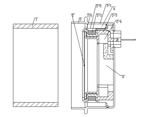
[0015] Embodiment 1: refer to Figure 1~3 . The ring gear positioning sleeve of the passive wheel speed sensor. The passive wheel speed sensor includes a housing 3 and a sensor sensing part 2. The sensor sensing part 2 is integrally injection molded and packaged, including a skeleton 2-3, a magnetic steel 2-4, The coil 2-2 and the ring gear 2-1, the bottom of the sensing part 2 of the sensor is connected to the bottom wall of the housing 3 by injection molding, and the center hole of the sensing part 2 of the sensor is provided with a positioning hole 4 near the bottom of the housing 3, and the sensor The outer wall 2-5 of the sensing part 2 is separated from the inner wall 3-1 of the housing 3 to form a gap 6. The ring gear positioning sleeve 1 is tubular, and the thickness of the tube wall is the distance between the outer wall 2-5 of the sensor sensing part 2 and the housing 3. There is a gap 6 between the inner walls 3-1, the outer wall of the ring gear positioning sleeve...
Embodiment 2
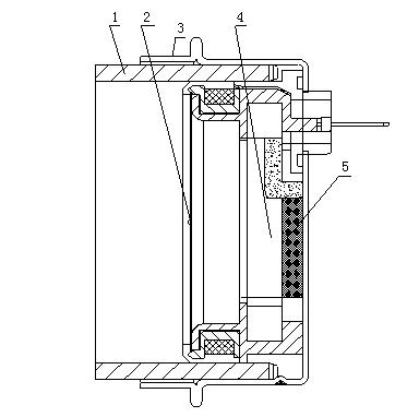
[0017] Embodiment 2: refer to Figure 4 . The ring gear positioning sleeve 1 is "convex" shape, the tube wall thickness of the smaller diameter end is the gap 6 between the outer wall 2-5 of the sensor sensing part 2 and the inner wall 3-1 of the housing 3, the ring gear positioning sleeve 1 The outer wall of the smaller diameter end matches the inner wall 3 - 1 of the housing 3 , its inner wall matches the outer wall 2 - 5 of the sensing part 2 of the sensor, and its outer stepped surface matches the opening of the housing 3 .
Embodiment 3
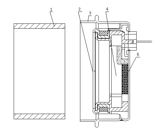
[0018] Embodiment 3: refer to Figure 1~3 . A ring gear positioning process for a passive wheel speed sensor, comprising the following steps: a. Embedding the front end of the ring gear positioning sleeve 1 into a space formed by the outer wall 2-5 of the sensor sensing part 2 and the inner wall 3-1 of the housing 3 In the gap 6, and the outer wall of the front end of the ring gear positioning sleeve 1 is connected with the inner wall 3-1 of the outer casing 3, and its inner wall is connected with the outer wall 2-5 of the sensor induction sleeve 2; b. Inject the ring into the positioning port 4 of the sensor induction sleeve 1 Oxygen resin 5 is used to make the second connection between the bottom of sensor sensing part 2 and the bottom wall of housing 3 through epoxy resin 5; c, after epoxy resin 5 is solidified, take out ring gear positioning sleeve 1.
PUM
 Abstract
Description
Claims
Application Information
 - R&D
- Intellectual Property
- Life Sciences
- Materials
- Tech Scout
- Unparalleled Data Quality
- Higher Quality Content
- 60% Fewer Hallucinations
Browse by: Latest US Patents, China's latest patents, Technical Efficacy Thesaurus, Application Domain, Technology Topic, Popular Technical Reports.
© 2025 PatSnap. All rights reserved.Legal|Privacy policy|Modern Slavery Act Transparency Statement|Sitemap|About US| Contact US: help@patsnap.com