
Capacitive voltage divider formed by a printed circuit board

A technology for printed circuit boards and capacitive voltage dividers, applied in the direction of voltage dividers, etc., can solve the problems of adverse effects on response speed, low measurement bandwidth of voltage dividing ratio of capacitive voltage dividers, and large coaxial structure volume, etc., to achieve easy processing , Good parasitic inductance, the effect of large capacitance value

Inactive Publication Date: 2010-08-04
XI AN JIAOTONG UNIV
View PDF4 Cites 10 Cited by
  • Summary
  • Abstract
  • Description
  • Claims
  • Application Information

AI Technical Summary

Problems solved by technology

However, the current coaxial structure is large in size, and the parasitic inductance of discrete components has an adverse effect on the response speed, and the voltage division ratio and measurement bandwidth of the capacitive voltage divider are low

Method used


Image

  • Capacitive voltage divider formed by a printed circuit board
  • Capacitive voltage divider formed by a printed circuit board
  • Capacitive voltage divider formed by a printed circuit board

Examples


Embodiment 1

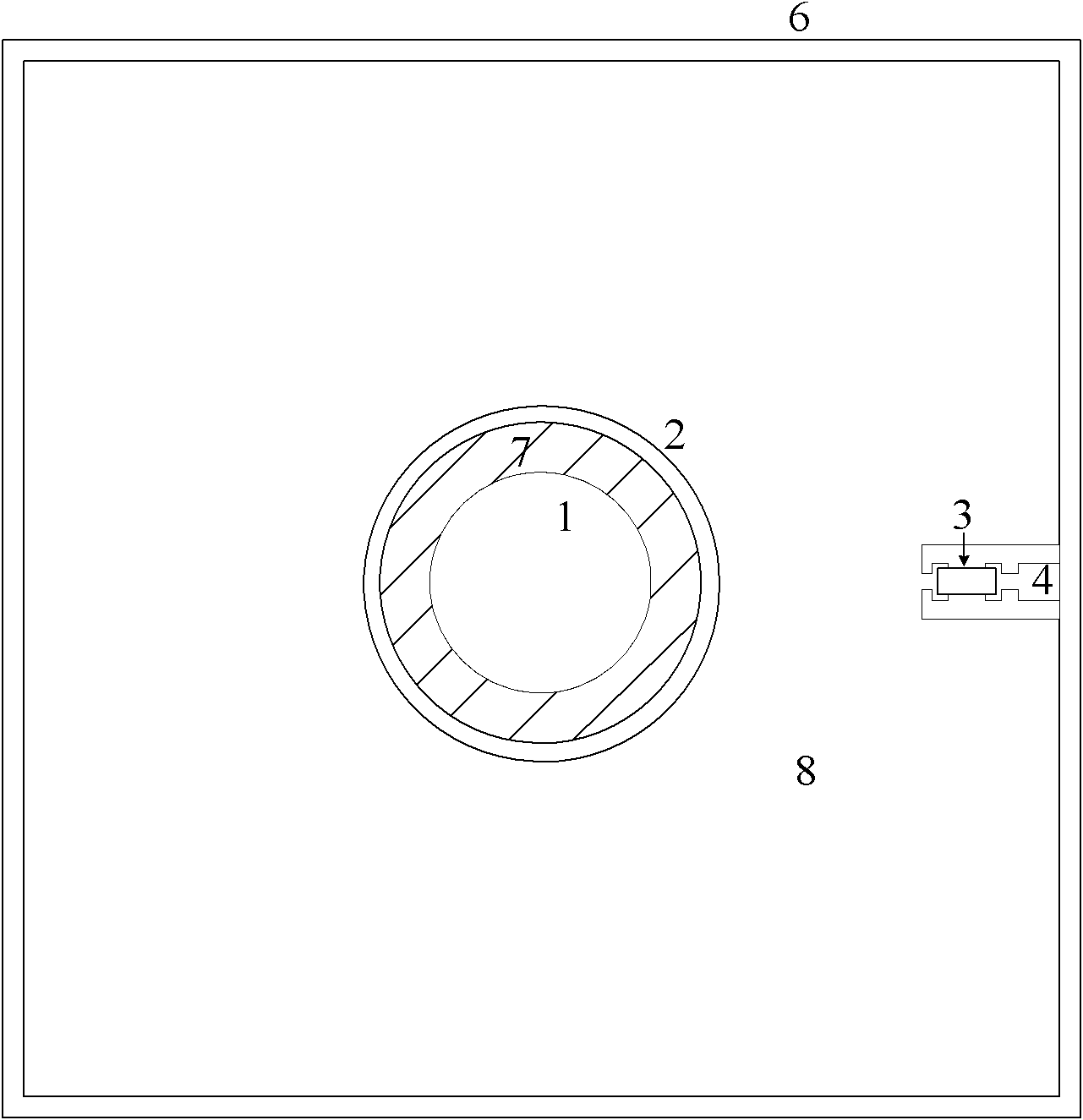
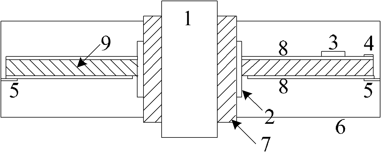
[0011] Embodiment 1: see figure 1 , 2. The present invention includes a grounding shell 6 and a high-voltage side bus bar 1 arranged in the grounding shell 6. An epoxy resin insulating part 7 is arranged between the high-voltage side bus bar 1 and the grounding shell 6, and the epoxy resin insulating part 7 The upper sleeve is equipped with a high-voltage implant electrode 2, and the high-voltage implant electrode 2 is equipped with a low-voltage arm of a capacitive voltage divider made of a double-layer printed circuit board. The low-voltage arm is composed of a base material 9 and printed on the base material. The surface is composed of a copper clad layer 8, the copper clad layer on one side is connected to the high voltage implanted electrode 2, and the ground terminal 5 connected to the ground shell 6 is arranged on the other side in four directions, and the capacitance of the low voltage arm Determined by the interlayer capacitance of the printed circuit board, the match...

Embodiment 2

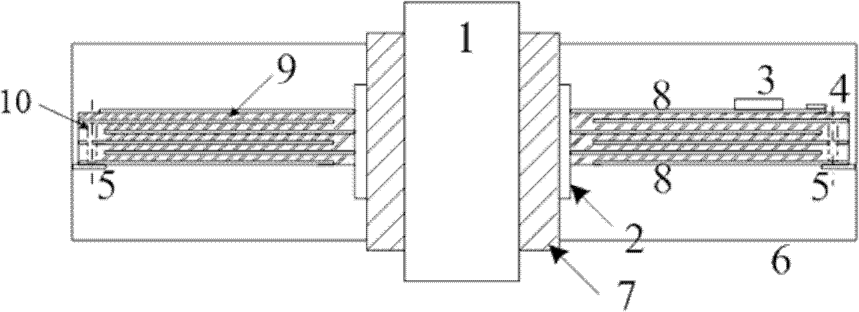
[0012] Example 2, see figure 1 , 3. In this example, when a multi-layer printed circuit board is used to form a low-voltage arm capacitor, the copper clad layers of the circuit board are divided into two groups, and the copper clad layers of different groups are isolated from each other, and the copper clad layers of the same group are connected by vias 10 , the two groups of copper clad layers are respectively connected to the voltage divider high-voltage implanted electrode 2 and the ground terminal 5 . Other connections are the same as in Embodiment 1.


PUM


Abstract

The invention relates to a capacitive voltage divider formed by a printed circuit board. The capacitive voltage divider is used for the measurement of rapid rise-time high-voltage pulse. The printed circuit board technology is used to design the low-voltage arm capacitor of the capacitive voltage divider. The design method can well control the parasitic inductance of a low-voltage arm. When a multilayer printed circuit board is adopted, large capacity can be realized at low cost, so the capacitive voltage divider with high voltage ratio and wide frequency band is realized. Moreover, according to the measurement principle of the capacitive voltage divider, by adopting large low-voltage arm capacitor capacity, the response pulse width is improved. By adopting the design method of using the printed circuit board to constructing the low-voltage arm capacitor, the invention has the advantages that the technological processing is easy, different shapes of the low-voltage arm can be designed according to the installation conditions of the system to be measured, and the capacitive voltage divider can be widely used for the measurement of high-voltage pulse and other transient voltage.

Description

technical field [0001] The invention relates to a capacitive voltage divider composed of a printed circuit board, in particular to a capacitive voltage divider composed of a printed circuit board used in pulse power technology or power system for nanosecond high-voltage pulse measurement. Background technique [0002] The voltage divider used for high-voltage pulse measurement mainly has two structures: resistive and capacitive. Due to the parasitic parameters of the resistance element of the voltage divider arm, the measurement frequency band of the resistor divider is greatly limited. When the pulse front speed to be measured is fast, the response characteristics cannot meet the measurement requirements. At the same time, the limited input impedance of the resistor divider is treated There is a certain influence on the circuit of the test system. [0003] At present, for pulses with a faster leading edge, the measurement method of a capacitor voltage divider is generally ...

Claims


Application Information

Patent Timeline
Patent Type & Authority Applications(China)
IPC IPC(8): G01R15/06
Inventor 翟小社耿英三王建华王妍刘志远张国钢
Owner XI AN JIAOTONG UNIV
Learn More