
Power electronic transformer having multi-winding isolation transformer

An isolation transformer, power electronics technology, applied in transformers, fixed transformers, circuits, etc., can solve the problems of increased complexity and manufacturing cost of power electronic transformers, and achieve the effects of improving power quality, fast voltage, and voltage regulation

Inactive Publication Date: 2010-08-04
INST OF ELECTRICAL ENG CHINESE ACAD OF SCI
View PDF6 Cites 20 Cited by
  • Summary
  • Abstract
  • Description
  • Claims
  • Application Information

AI Technical Summary

Problems solved by technology

The disadvantage of these structures is that in the case of high voltage input, it adds complexity and manufacturing cost to the engineering realization process of multi-level cascaded power electronic transformers such as control and installation.

Method used


Image

  • Power electronic transformer having multi-winding isolation transformer
  • Power electronic transformer having multi-winding isolation transformer
  • Power electronic transformer having multi-winding isolation transformer

Examples


Embodiment Construction

[0022] The present invention will be further described below in conjunction with the accompanying drawings and specific embodiments.

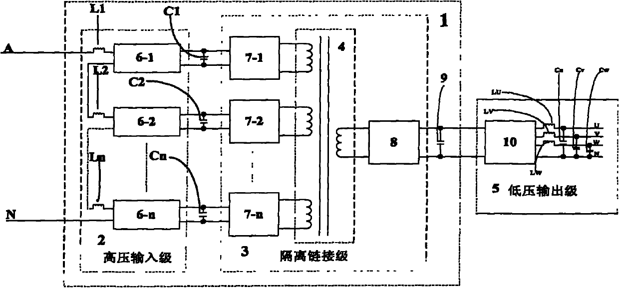
[0023] figure 1 Shown is a single-phase input, three-phase four-wire output power electronic transformer composed of a basic unit module 1 and a low-voltage output stage 5 of the present invention.

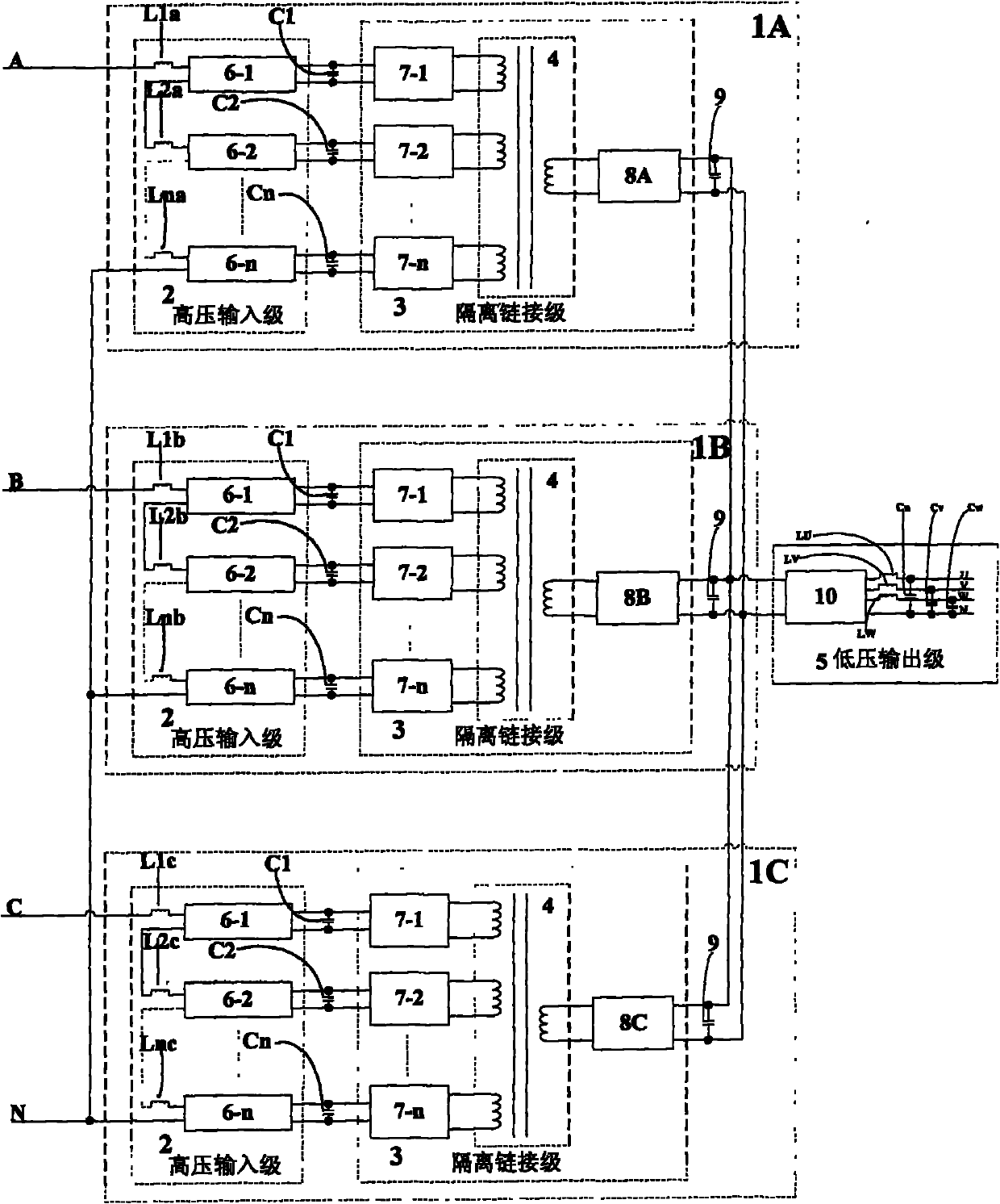
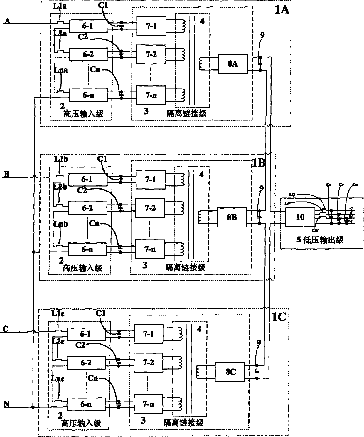
[0024] The basic unit module 1 is composed of a high-voltage input stage 2 and an isolation link stage 3 . The high-voltage input stage 2 is formed by cascading n H-bridge AC-DC power conversion modules 6-1, 6-2, ... 6-n (n is an integer greater than 1), and each H-bridge AC-DC The AC input side of the power conversion module (6-1, 6-2, ... 6-n) is connected to an AC input inductor (L1, L2, ... Ln) (n is an integer greater than 1), each H bridge The DC output side of the type AC-DC power conversion module is connected in parallel with a DC bus energy storage capacitor (C1, C2, ... Cn) (n is an integer greater than 1). One end of the cascaded fir...


PUM


Abstract

A power electronic transformer having a multi-winding isolation transformer comprises a power electronic transformer basic unit module (1) connected with an isolation transformer having multiple input windings and single output winding and a low voltage output stage (5). The basic unit module (1) can form the power electronic transformer with single-phase or three-phase four-line input and three-phase four-line output. The basic unit module (1) comprises a high voltage input stage (2) and an isolation link stage (3). The high voltage input stage (2) is in serial connection and cascade connection through n-stage H bridge type power conversion modules. The isolation link stage (3) comprises a medium frequency or high frequency isolation transformer (4) having n groups of input windings and one group of output winding, n groups of H bridge type DC-AC power converts and a group of H bridge type AC-DC power converter (8). The low voltage output stage (5) comprises a three-phase four-line DC-AC voltage source inverter (10) connected with a common direct current bus.

Description

technical field [0001] The invention relates to a power electronic transformer. Background technique [0002] Power transformers are the basic components of power systems. Its outstanding advantages are simple manufacturing process, high reliability and low price; but this kind of power transformer can only realize a single voltage level transformation and isolated transmission of electric energy, but the distortion of the grid voltage and current is caused by the nonlinearity of ferromagnetic components. Harmonic pollution is generated, and the secondary voltage cannot be kept constant. It does not have the ability to continuously adjust and comprehensively control voltage and current, and cannot realize the interaction with other equipment in the power grid. It cannot meet the requirements of the future smart grid. Power electronic transformer is a new type of intelligent power equipment that can be used for power system power conversion and transmission, which has emerge...

Claims


Application Information

Patent Timeline
Patent Type & Authority Applications(China)
IPC IPC(8): H02M5/45H02M7/521H01F30/06
Inventor 王平李耀华李子欣朱海滨胜晓松
Owner INST OF ELECTRICAL ENG CHINESE ACAD OF SCI
Learn More