Device for guiding airflow to impact liquid level in tangential direction for forming moisture-containing airflow

A technology of airflow and liquid level, applied in the direction of using liquid separating agent, liquid fuel supply/distribution, combustion method, etc., can solve the problems of low dust removal efficiency of dust removal device, increased motor power of induced draft fan, low dust removal efficiency, etc., and achieves compact structure. , The effect of improving thermal efficiency and convenient operation and maintenance

Inactive Publication Date: 2010-08-11
SHANGHAI UNIV OF ENG SCI
View PDF0 Cites 13 Cited by
  • Summary
  • Abstract
  • Description
  • Claims
  • Application Information

AI Technical Summary

Problems solved by technology

The dust removal device is a device for dust removal treatment of exhaust gas discharged from various operations such as boilers, medicine copying machines, casting workshops, brick kilns, wood processing, central air conditioning, range hoods, etc. Commonly used dust removal devices include cyclone dust collectors and bag dust collectors. These dust removal devices have their own characteristics, advantages and disadvantages, and are also suitable for some occasions. However, due to the different shapes and sizes of dust particles, such as: in wood processing The generated dust such as small pieces of wood, shavings, and wood chips has a large difference in mass and weight. For this mixed dust, only using a cyclone separator or a bag filter cannot solve the dust removal problem well, and the dust removal efficiency is low; another example: When removing dust from the flue gas produced by boilers and brick kilns, due to the high temperature of the flue gas, the general dust collector is not suitable, and the water film dust removal method is usually used, but due to the large resistance of the water film dust removal device, the induced draft fan The power of the motor increases, and the power consumption is large. The dust removal efficiency of the dust removal device is low and the energy consumption is large, which affects energy saving.

Method used


Image

  • Device for guiding airflow to impact liquid level in tangential direction for forming moisture-containing airflow
  • Device for guiding airflow to impact liquid level in tangential direction for forming moisture-containing airflow
  • Device for guiding airflow to impact liquid level in tangential direction for forming moisture-containing airflow

Examples


Embodiment Construction

[0033] The structure of the present invention will be further described in detail below in conjunction with the accompanying drawings.

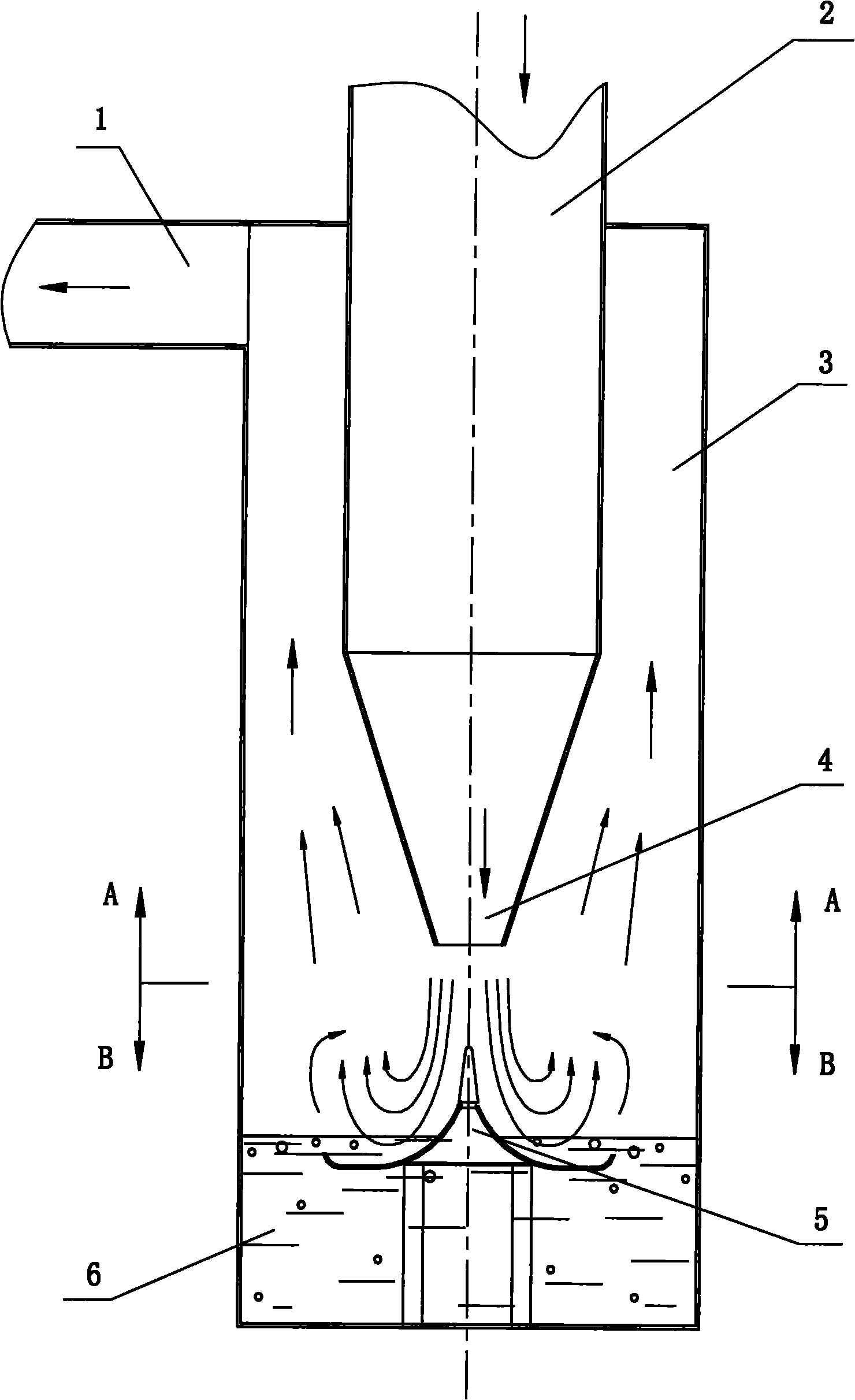
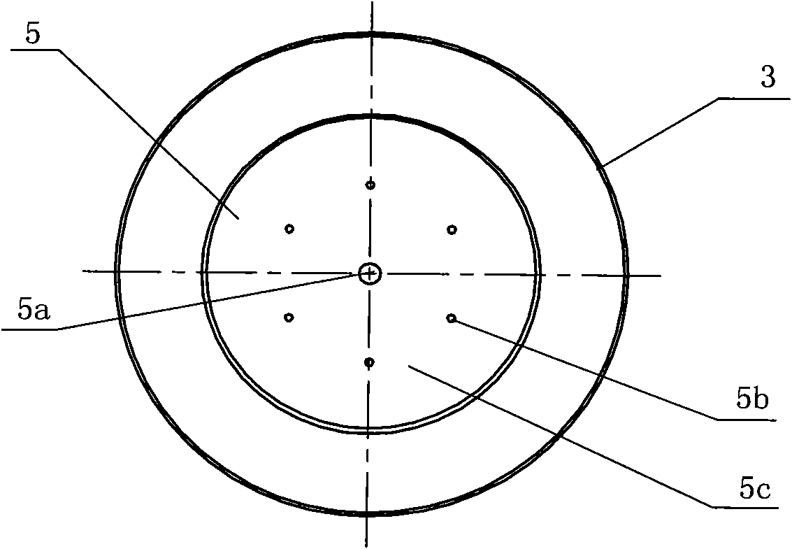
[0034] A device that guides the airflow to impact the liquid surface tangentially to form a wet airflow. A conical spout 4 connected to the vertically downward air inlet pipe 2 is set in the container 3. The liquid 6 is below the spout 4, which is in the shape of an inverted umbrella. The lower part of the airflow cyclone 5 is immersed in the liquid level of the liquid 6, and an air outlet 1 is drawn on the passage between the inner wall of the container 3, the air inlet pipe and the outer wall of the spout 4; the middle of the airflow cyclone 5 protrudes upwards Spire 5a, then be the arc-shaped surface 5c that is extended to the edge with a certain curve shape first down to the edge and then slightly upwards; Consistent shape, round or polygonal. When the airflow hits the airflow cyclone 5 downward, under the guidance of the curved surface ...


PUM


Abstract

The invention relates to a device structure used in the fields of liquefied natural gas heating gasification, natural gas heating, dust removal, central air-conditioning systems and the like. A device for guiding airflows to impact the liquid level in a tangential direction for forming moisture-containing airflows is characterized in that a conical spraying opening (4) communicated with a vertical downward airflow air inlet pipe (2) is arranged in a container (3), liquid (6) is arranged under the spraying opening (4), the lower part of an airflow swirl water element (5) in a reverse umbrella shape is soaked in the liquid (6), an airflow outlet (1) is led out on a passage formed between the inner wall of the container (3) and the outer walls of the air inlet pipe (2) and the spraying opening (4), the middle of the airflow swirl water element (5) is an upwards projected pointed top (5a) and then is an arc-shaped curve surface (5c) formed by being upwards bended a little after firstly going downwards to an edge by a curve line shape extending from the pointed top to the edge, and the horizontal projection of the outer ring of the airflow swirl water element (5) has the same shape as the horizontal cross section of the spraying opening (4) and is in a circular shape or a polygon shape. The invention has the advantages of simple structure and no movable component, is applicable to various kinds of strengthened heat transfer, has the functions of dust removal, humidifying purification and the like, and improves the heat efficiency and the dust removing efficiency.

Description

technical field [0001] The invention is a device structure used in the fields of liquefied natural gas heating and gasification, natural gas heating, dust removal, and centralized air-conditioning systems, and specifically relates to heating by guiding high-speed airflow tangentially impacting the liquid surface to form a wet vortex airflow , dust removal, humidification and purification functions. Background technique [0002] Energy conservation and emission reduction is a top priority in today's world, and our country also attaches great importance to it as a basic national policy. [0003] 1. In terms of energy saving, improving the thermal efficiency of various heat exchange devices is one of the key technologies. Liquefied natural gas heating gasifier and natural gas heating furnace are widely used heating devices in the natural gas industry. Today, natural gas is increasingly valued as a clean energy source. Improving the thermal efficiency of such devices is an urge...

Claims


Application Information

Patent Timeline
Patent Type & Authority Applications(China)
IPC IPC(8): F23K5/22B01D47/00
Inventor 严平曹伟武钱尚源刘伟军
Owner SHANGHAI UNIV OF ENG SCI
Why Eureka
Try Eureka