Material distributing method and device of circular cooler

A technology of material distributing device and ring cooler, which is applied in the direction of processing discharged materials, furnaces, lighting and heating equipment, etc., and can solve the problem of poor segregation effect of the material distribution device of the ring cooler, large power consumption of the blower motor, and cooling effect of the ring cooler To achieve the effect of simple structure, easy production and installation, and fast laying speed

Active Publication Date: 2010-08-11
ZHONGYE-CHANGTIAN INT ENG CO LTD
View PDF5 Cites 12 Cited by
  • Summary
  • Abstract
  • Description
  • Claims
  • Application Information

AI Technical Summary

Problems solved by technology

[0003] The segregation effect of the distribution device of the ring cooler used in actual production is poor. After the hot sinter is distributed on the trolley by the distribution device, the particle size of the hot sinter at the upper, middle and bottom is roughly the same in the height direction of the material layer, and The bottom layer is covered with small-sized hot sintered ore, which makes it difficult for the cooling air to penetrate the material layer or the resistance to penetrate the material layer is relatively large during blast cooling, the cooling effect of the ring cooler is poor, and the power consumption of the blower motor is large
In order to change

Method used


Image

  • Material distributing method and device of circular cooler
  • Material distributing method and device of circular cooler
  • Material distributing method and device of circular cooler

Examples


Embodiment Construction

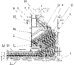
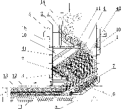
[0024] figure 1 It shows an embodiment of laying sintered ore on the circulating cooler trolley 5 by using the circulating cooler distribution method of the present invention. It is layered to pave the sintered ore on the circulating cooler trolley 5. Granular sinter 11 is mainly used, the sinter laid in the middle layer is mainly small-grain sinter 12, and the sinter laid on the top layer is mainly medium-grain sinter 13. Among them, the particle size of the large particle size sinter 11 is 40 mm to 150 mm, the particle size of the medium particle size sinter 13 is 10 mm to 40 mm, and the particle size of the small particle size sinter 12 is less than 10 mm. The thickness of the large, medium, and small grain size zones is related to the grain composition of the input mixed sinter, and is variable. Generally speaking, the bottom sinter thickness L1 mainly composed of the large grain size sinter 11 is 400mm~600mm, and the small The thickness L2 of the middle layer sinter with t...


PUM

PropertyMeasurementUnit
Granularityaaaaaaaaaa

Abstract

The invention discloses a material distributing method of a circular cooler, which is characterized by laying three layers of sinter ore on a trolley of the circular cooler and mainly laying large-grain sinter ore on the bottom layer, small-grain sinter ore on the middle layer and the intermediate-grain sinter ore on the top layer. The method has the advantages of good segregation effect, capability of improving the work environment of the circular cooler and prevention of the waste of the raw material. The invention further discloses a material distributing device of the circular cooler, which is used for the material distributing method of the circular cooler; the material distributing device of circular cooler comprises a material distributing cylinder which is internally provided with a lower slide plate for stacking the sinter ore in the material distributing cylinder; a segregation material distributing slide plate for delivering the sinter ore to the top of the material pile is arranged above the lower slide plate; a front inclined surface and a rear inclined surface are formed on the material pile by the lower slide plate and the segregation slide plate; and the rear inclined surface has the same inclination direction with the segregation slide plate. The device can lay the large-grain sinter ore on the bottom layer of the trolley of the circular cooler, the small-grain sinter ore on the middle layer of the trolley of the circular cooler and the intermediate-grain sinter ore on the top layer of the trolley of the circular cooler.

Description

Technical field [0001] The invention relates to a method and a device for distributing materials in a sintering process, and in particular to a method and device for distributing materials at the feed of an annular cooler. Background technique [0002] The distributing device of the ring cooler is located between the discharge hopper of the sintering machine and the ring cooler trolley. The hot sintered ore crushed by the single-roller crusher enters the distributing device of the ring cooler from the discharge hopper of the sintering machine, and then is arranged on the ring cooler trolley through the distributing device of the ring cooler. The specially arranged structure in the distributing device determines the ring cooler platform The cloth effect on the car, such as the flatness and segregation degree of the cloth. [0003] The distribution device of the ring cooler used in actual production has poor segregation effect. After the hot sinter is distributed on the trolley thro...

Claims


Application Information

Patent Timeline
IPC IPC(8): F27D3/00F27D15/02
Inventor 周胜良刘相佩戴传德刘克俭陈乙元郑炯科郭清周慧玲
Owner ZHONGYE-CHANGTIAN INT ENG CO LTD
Why Eureka
Try Eureka