
Vehicle engine electronic control unit testing system and variable resistor combination adjusting method thereof

A vehicle engine and electronic control unit technology, which is applied in engine testing, vehicle testing, and machine/structural component testing. , the effect of convenient operation

Inactive Publication Date: 2011-08-31
TIANJIN UNIV
View PDF0 Cites 0 Cited by
  • Summary
  • Abstract
  • Description
  • Claims
  • Application Information

AI Technical Summary

Problems solved by technology

Due to the high cost, high risk, cumbersome process, and inconvenient operation, the actual vehicle test is generally only carried out in the final stage of the development or calibration of the engine management system, and the simulation test (that is, the test in the simulated test environment) is often used during the development process.
[0004] The simulation test has a simulation test based on a special real-time simulator, which requires the design, development or purchase of complex and expensive motor vehicle and engine simulators; the simulation test also has a simple test method based on a signal generator and an oscilloscope. The signal generator generates the excitation source signal, excites the engine electronic control unit, and then detects the output signal of the engine control system through an oscilloscope. This type of test is completed by a general electronic control product development equipment such as a signal generator, an oscilloscope or a logic analyzer. The equipment is simple, but the test is inconvenient

Method used


Image

  • Vehicle engine electronic control unit testing system and variable resistor combination adjusting method thereof
  • Vehicle engine electronic control unit testing system and variable resistor combination adjusting method thereof
  • Vehicle engine electronic control unit testing system and variable resistor combination adjusting method thereof

Examples


Embodiment Construction

[0041] The vehicle engine electronic control unit testing system and the variable resistor combination adjustment method thereof of the present invention will be described in detail below in conjunction with the embodiments and the accompanying drawings.

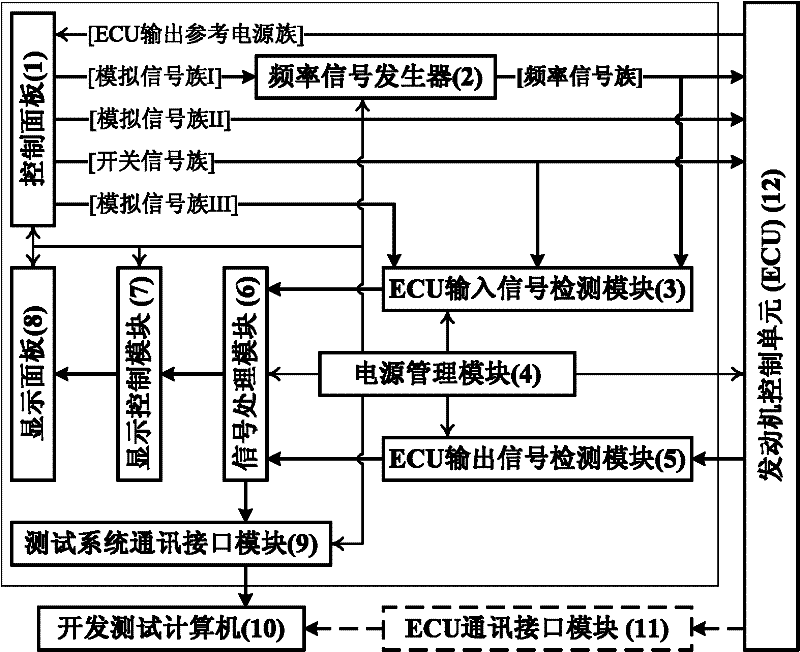
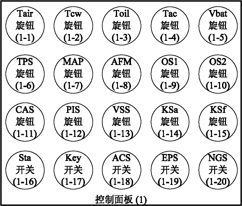
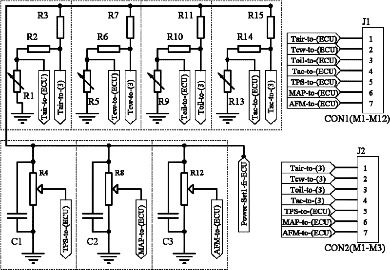
[0042] Such as figure 1As shown, the vehicle engine electronic control unit testing system of the present invention includes: a control panel 1; a frequency signal generator module 2; an ECU input signal detection module 3; a power management module 4; an ECU output signal detection module 5; a signal processing module 6; display control module 7; display panel 8 and test system communication interface module 9. Wherein, the signal processing module 6 detects the sensor simulation signal of the simulated vehicle and engine operation generated by the control panel 1 and the frequency signal generator module 2 through the ECU input signal detection module 3; the signal processing module 6 passes through the ECU The output sig...


PUM


Abstract

The invention relates to a vehicle engine electronic control unit testing system and a variable resistor combination adjusting method thereof. A signal processing module detects sensor simulation signals for simulating the operation of a vehicle and an engine, which are generated by a control panel and a frequency signal generator module, through an ECU (Electronic Control Unit) input signal detection module; actuator control signals of an engine management system, which are output by an engine control unit, are detected through an ECU output signal detection module; the testing state, condition parameters and tested engine control unit performance data are displayed on a display panel through a display control module; and the testing state, the condition parameters and the tested engine control unit performance data are transmitted to a computer for development and analysis through a testing system communication interface module. In the invention, the sensor simulation signals of theengine management system are generated in real time so as to stimulate the engine control unit, and meanwhile, the simulation signals and the actuator control signals output by the ECU are detected, and data are transmitted, analyzed, processed, displayed and communicated.

Description

technical field [0001] The invention relates to a vehicle engine, in particular to a vehicle engine electronic control unit testing system and a variable resistor combination adjustment method suitable for testing and checking the control performance of the engine control module in a simulated environment. Background technique [0002] Vehicle engine electronic control technology is a comprehensive technology integrating computer technology, electronic technology, testing technology, precision manufacturing technology, and engine technology. 1. The basic way to increase the power is the best means to improve the power performance and safety performance of the engine, and it is also the underlying and core technology of vehicle electronic technology. With the development of the vehicle industry, the electronic control technology of vehicle engines is not only developing. Especially in China, the development and testing of vehicle engine control management system has become a...

Claims


Application Information

Patent Timeline
Patent Type & Authority Patents(China)
IPC IPC(8): G01M17/007G01M15/00
Inventor 于镒隆刘昌文张俊红王韬王爽张宝欢
Owner TIANJIN UNIV
Learn More