
IPM motor and vacuum inhaling apparatus using the same

A technology for suction devices and motors, applied in electromechanical devices, parts of pumping devices for elastic fluids, liquid fuel engines, etc., can solve cogging torque and reluctance torque fluctuations, gap magnetic flux density changes and Current distortion and other problems, to achieve the effect of uniform distribution of magnetic flux density, reduced power consumption, and increased suction efficiency

Inactive Publication Date: 2010-08-11
AMOTECH
View PDF0 Cites 27 Cited by
  • Summary
  • Abstract
  • Description
  • Claims
  • Application Information

AI Technical Summary

Problems solved by technology

[0015] As mentioned above, the existing IPM type BLDC motor will generate torque fluctuations when power is supplied to the stator coil, and the torque fluctuations will inevitably lead to changes in the gap magnetic flux density and current distortion. Therefore, cogging torque and reluctance rotation will be generated. Moment fluctuation

Method used


Image

  • IPM motor and vacuum inhaling apparatus using the same
  • IPM motor and vacuum inhaling apparatus using the same
  • IPM motor and vacuum inhaling apparatus using the same

Examples


Embodiment Construction

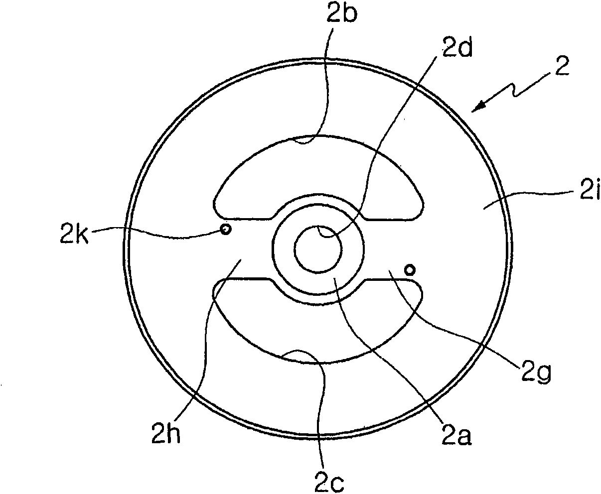
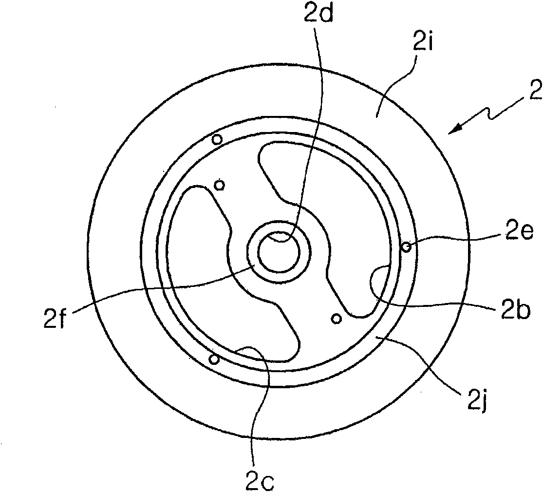
[0061] Hereinafter, the present invention will be described in detail through examples. The same reference numerals in the respective drawings denote the same components.

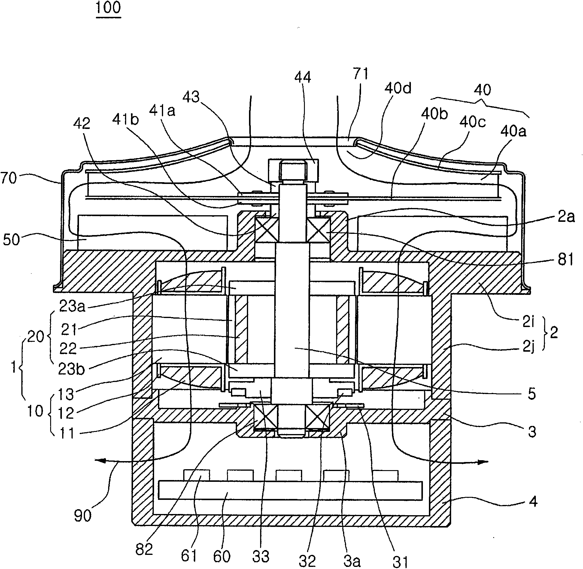
[0062] figure 1 It is a cross-sectional view showing a vacuum suction device of a vacuum cleaner using an IPM motor according to an embodiment of the present invention.

[0063] refer to figure 1 , the vacuum suction device 100 of the present invention includes: an IPM motor 1, which is composed of a stator 10 and a rotor 20, and generates rotational force; an upper housing 2, which protects the upper part and the outer peripheral surface of the IPM motor 1; an intermediate housing 3, which The peripheral part is fixedly combined with the lower end of the upper casing 2, and supports the IPM motor 1; the rotating shaft 5 is fixedly combined with the center of the rotor 20 and can rotate; the impeller 40 is located on the upper part of the rotor 20, Fixedly combined with the upper end of the rotating shaf...


PUM


Abstract

Provided is a high speed and high efficiency IPM (Interior Permanent Magnet) motor and a slim type vacuum inhaling apparatus using the same, which establishes a passage path of introduced air into a path of air-cooling the inside of a stator and a circuit element to thus cool heat that is produced from the IPM motor without a special heat radiator. The IPM motor includes: a stator having a number of tees which are protruded so as to form a number of slots on the inner circumferential wall of a cylindrical body, and a stator coil which is partially wound around the slots; and an IPM type rotor having a rotor core at the central side of which a rotating shaft is mounted, and a number of permanent magnets which are fitted into a number of permanent magnet insertion holes which are formed on the identical circumference of the rotor core, and which is rotated by the stator. The permanent magnet includes a first group of permanent magnets and a second group of permanent magnets which wholly have two-pole magnetic pole structure and form a first spacer and a second spacer between the first group of permanent magnets and the second group of permanent magnets to prevent the leakage of magnetic flux in the circumference direction.

Description

technical field [0001] The present invention relates to an IPM (Interior Permanent Magnet: built-in permanent magnet) motor and a vacuum suction device using the motor. A high-speed, high-efficiency IPM motor and a thin vacuum suction device using this motor are provided to air-cool the interior of the stator and circuit components so that cooling can be achieved without additional heat sinks. Background technique [0002] Currently, many home appliances have been developed and sold on the market, including a vacuum cleaner for cleaning living environments. [0003] A vacuum cleaner is a household appliance that uses the vacuum pressure generated by the impeller installed inside the vacuum cleaner body and the BLDC (Brushless DC: brushless direct current) motor to suck in air containing foreign matter such as dust, and then filter (filter) the foreign matter inside the body. product. [0004] In this type of vacuum cleaner, in order to generate vacuum pressure, the vacuum ...

Claims


Application Information

Patent Timeline
Patent Type & Authority Applications(China)
IPC IPC(8): F04D25/06
CPCF04D25/082F04D25/0606F04D29/5806F04D25/06H02K7/00F04B9/00
Inventor 李正勋
Owner AMOTECH
Learn More