Automatic wing-body docking hole-making system and method

An automatic manufacturing and wing body technology, which is applied in the direction of manufacturing tools, milling machine equipment details, milling machine equipment, etc., can solve problems such as large working space

Inactive Publication Date: 2010-08-18
NANJING UNIV OF AERONAUTICS & ASTRONAUTICS +1
View PDF7 Cites 29 Cited by
  • Summary
  • Abstract
  • Description
  • Claims
  • Application Information

AI Technical Summary

Problems solved by technology

Therefore, the device has great randomness in the positioning process
At the same time, the system requires a large working space during the positioning process,

Method used


Image

  • Automatic wing-body docking hole-making system and method
  • Automatic wing-body docking hole-making system and method
  • Automatic wing-body docking hole-making system and method

Examples


Embodiment Construction

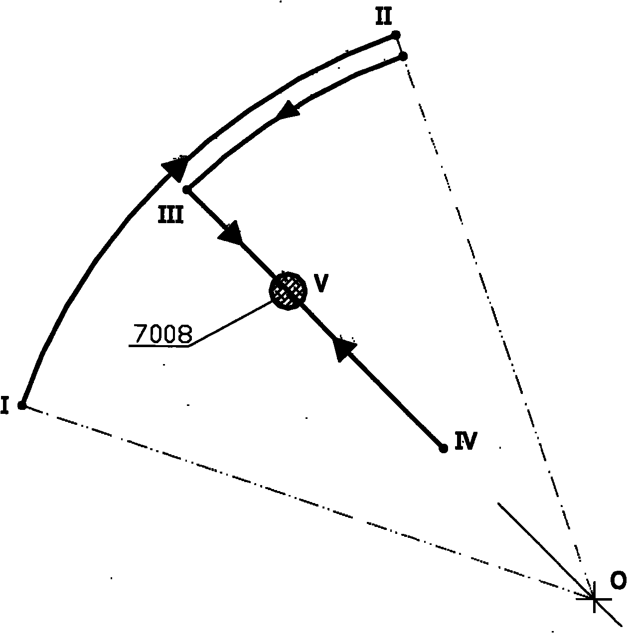
[0040] The automatic hole-making method and system for wing-body docking of the present invention mainly uses the principle of magnetic positioning to first determine the projection position of the blind hole on the outer surface of the wing body and make a mark point, and actively obtains the mark point in the automatic hole-making device through optical detection technology. The pose in the coordinate system, and finally control the hole-making unit to complete the machining of the hole according to the pose of the marked point. The specific implementations of the method and device of the present invention will be described in detail below in conjunction with the accompanying drawings.

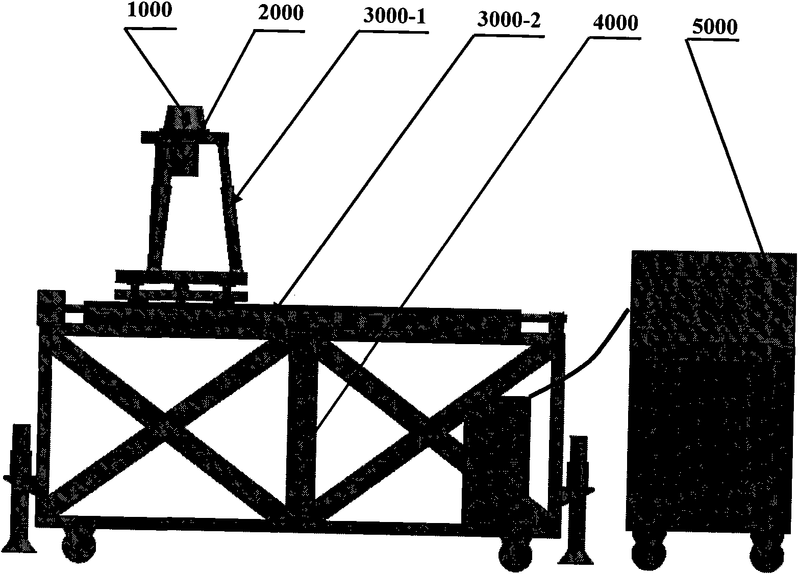
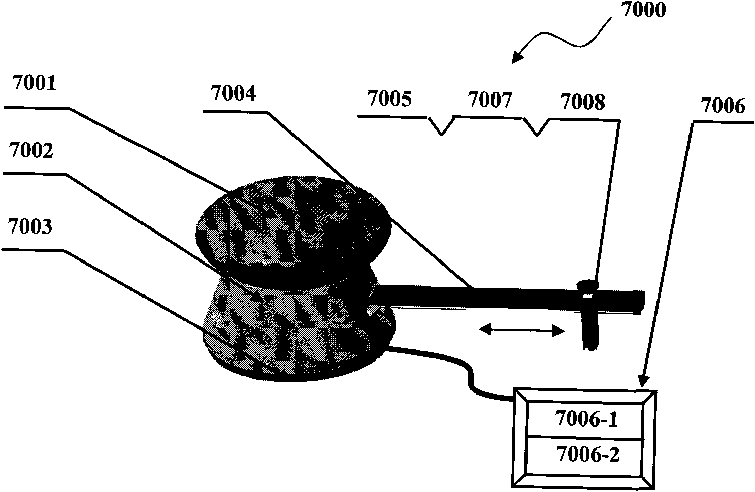
[0041] figure 1 , figure 2 , image 3 , Figure 4 , Figure 5 , Figure 6 ,and Figure 7 , is a specific implementation case of the wing-body docking automatic hole-making system of the present invention, which includes a hole positioning unit 7000, a hole-making unit 1000, a normal v...


PUM


Abstract

The invention relates to an automatic wing-body docking hole-making system and a method, which belongs to the technical field of operating transport. The method comprises the following steps: mainly utilizing the principle of magnetic positioning to firstly determine the projection position of a blind hole on the outer surface of a wing body and make a mark point; secondly, determining the pose of the mark point in a coordinate system of a hole-making device by image processing technique; and finally, generating corresponding motion control instructions to control a hole making unit to complete the processing of the hole according to the pose of the mark point. The system mainly comprises a hole positioning unit (7000), the hole making unit (1000), a normal vector detection unit (2000), a normal vector pose-adjusting mechanism (3000), a movable vehicle body (4000) and a central control unit (5000). The method and the system can better solve the processing problem of wing-body docking connecting holes.

Description

technical field [0001] The invention relates to an automatic hole-making system and method for wing-body docking, and belongs to the technical field of operation transportation. Background technique [0002] Docking hole making is a key link in the assembly of wing and body. The efficiency of hole making directly restricts the aircraft assembly cycle, and the quality of hole making will also directly affect the fatigue resistance of the connected structural parts. Especially with the development of thin-walled, integrated and complex aerospace structural parts, the requirements for long life, high quality and high efficiency of the whole machine structure, and the large increase in the amount of difficult-to-machine materials such as composite materials and titanium alloys, Make assembly holes more demanding and more precise than before. [0003] Due to the influence of factors such as difficult positioning and clamping of the processing parts, narrow working environment, a...

Claims


Application Information

Patent Timeline
IPC IPC(8): B23B35/00B23C3/00
Inventor 何宁李亮单以才杨吟飞赵威卞荣秦晓杰陈建立
Owner NANJING UNIV OF AERONAUTICS & ASTRONAUTICS
Why Eureka
Try Eureka