Numerical control laser cutting machine

A digitally controlled laser and cutting machine technology, applied in laser welding equipment, welding equipment, metal processing equipment, etc., can solve problems such as direct blanking, high manufacturing cost, and huge structure

Inactive Publication Date: 2010-08-18
扬州宏华激光技术有限公司
View PDF6 Cites 10 Cited by
  • Summary
  • Abstract
  • Description
  • Claims
  • Application Information

AI Technical Summary

Problems solved by technology

This kind of laser cutting machine can only be used for cutting plates, but not for cutting cloth. It is mainly caused by the following defects that it cannot cut cloth. The cloth is a soft material and cannot slide freely; on the other hand, after the plate is cut, it can be dropped directly, while the overall soft fabric needs to be provided with a support device at the bottom of the ground, and the material cannot be dropped directly after cutting. Therefore, the feeding device does not It is suitable for processing soft materials; moreover, the existing CNC laser cutting machine uses a rack and pinion transmission mechanism for the laser head to move along the X-axis and Y-axis, which has a complex structure, a large structure, and high manufacturing costs.

Method used


Image

  • Numerical control laser cutting machine
  • Numerical control laser cutting machine
  • Numerical control laser cutting machine

Examples


Embodiment Construction

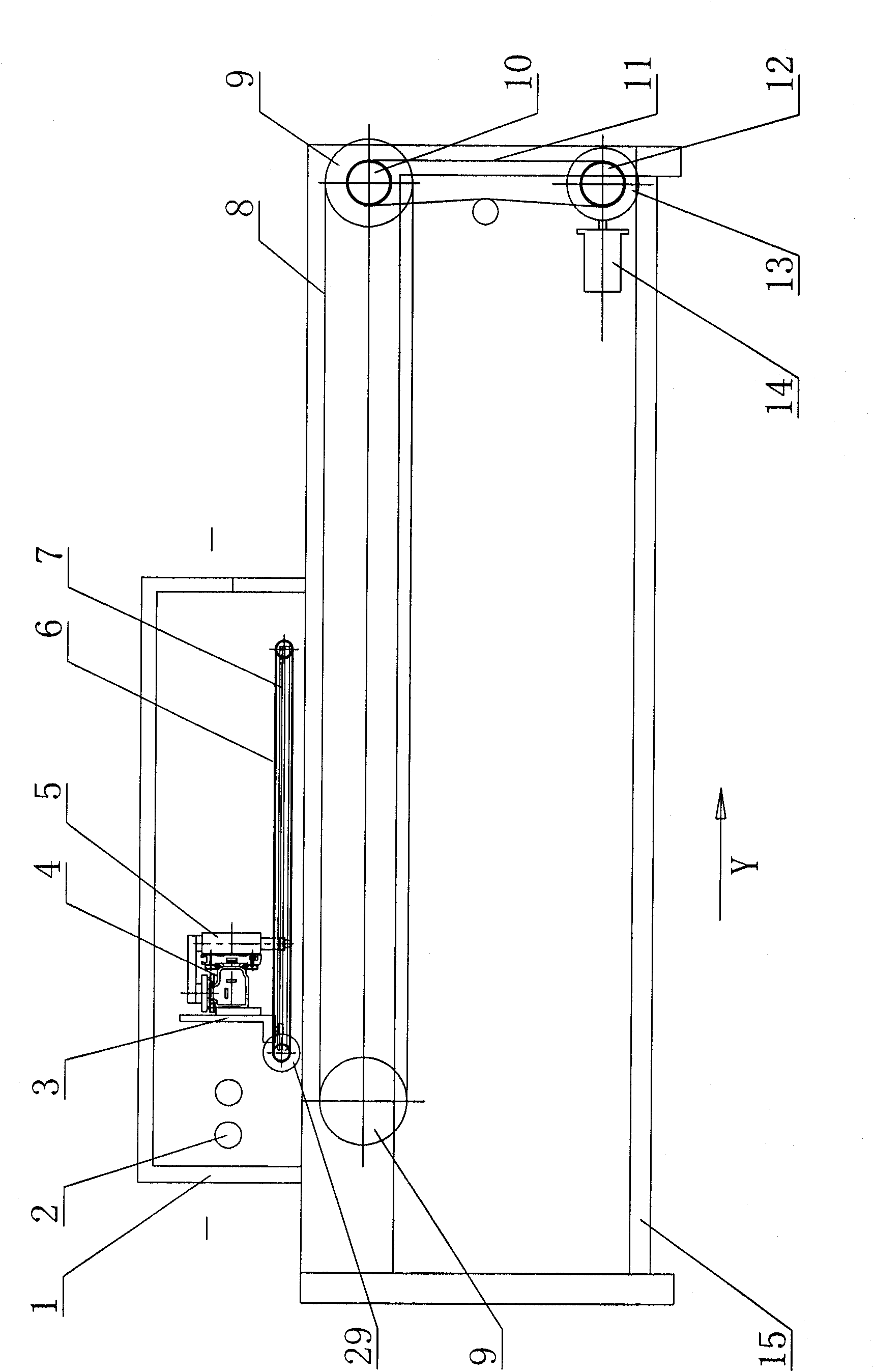
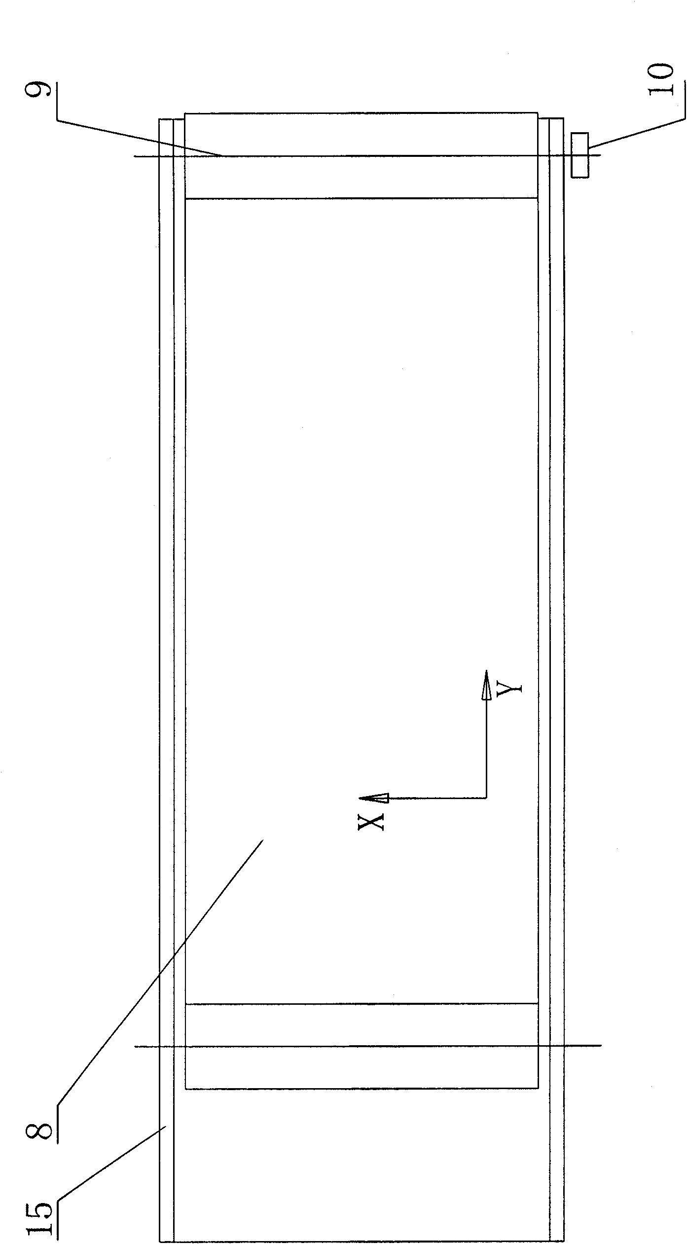
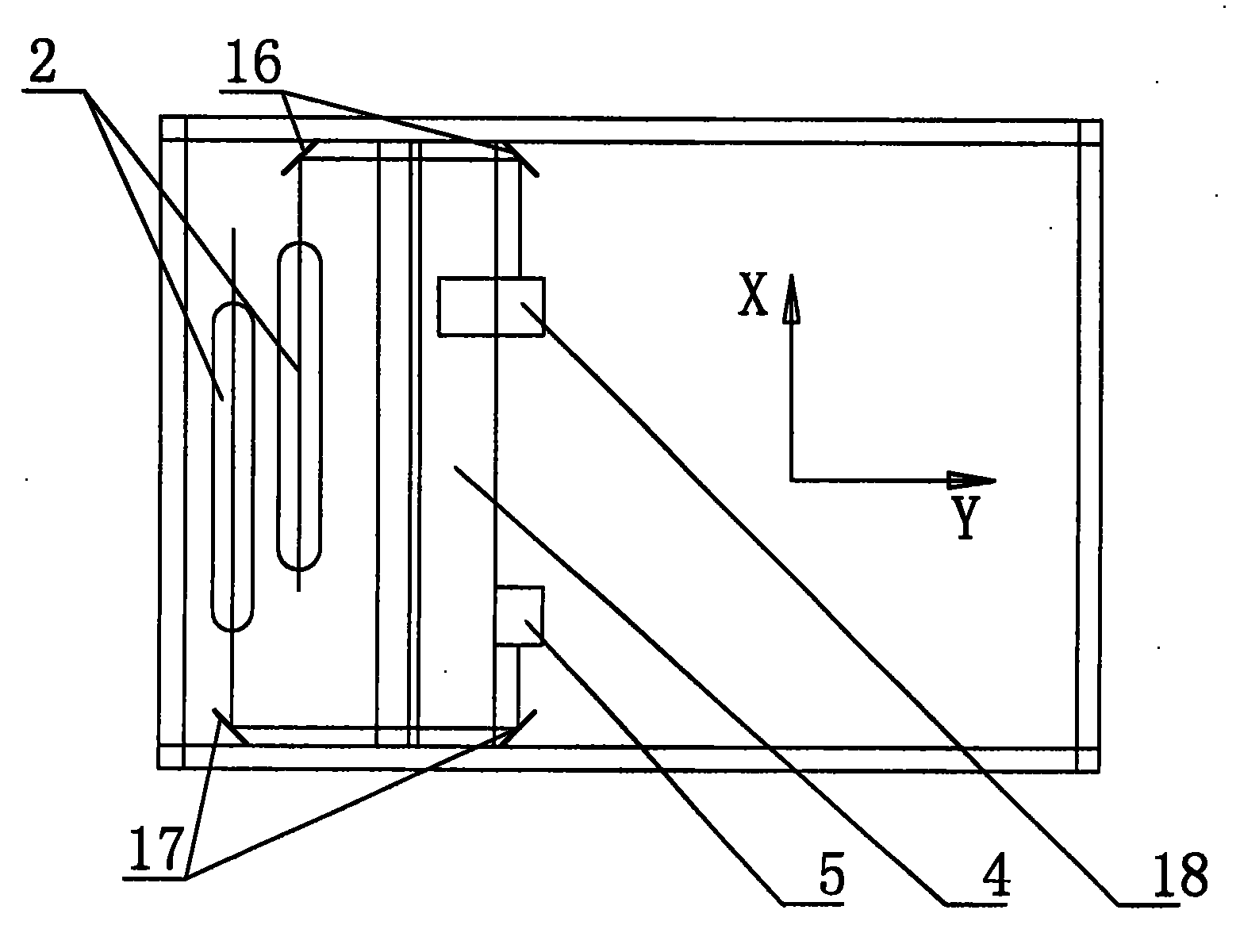
[0016] Such as Figure 1-5 As shown, it is a laser cutting machine, its structure mainly includes a fuselage 15, two laser generators 2 are arranged on the fuselage 15, and two sets of mirrors 16, 17 are arranged on the fuselage corresponding to the laser generator 2 Two groups of reflectors 16, 17 are located on both sides of the fuselage 15, corresponding to the two laser heads 5, 18 that can move along the X-axis and Y-axis, and the fuselage is horizontally provided with two rubber rollers whose axes are parallel 9. A conveyor belt 8 is wound on the rubber roller 9, and the conveyor belt 8 is composed of steel wires connected to each other to form a mesh. The end of any rubber roller is provided with a sprocket 10, and the sprocket 10 is connected to the feeding step by the chain 11. The sprocket 12 at the output shaft end of the reducer 13 of the motor 14 shaft belt is connected in transmission.

[0017] In order to make the laser head 5,18 move along the Y axis on the fu...


PUM


Abstract

The invention discloses a numerical control laser cutting machine, which belongs to the field of cutting devices. The numerical control laser cutting machine comprises a machine body, wherein a laser generator is arranged on the machine body; a reflector corresponding to the laser generator is arranged on the machine body; the reflector corresponds to a laser head moving along an X axis and a Y axis; two rubber covered rollers, the axes of which are parallel to each other, is horizontally arranged on the machine body; conveying belts are wound on the rubber covered rollers; the end part of any one of the rubber covered rollers is provided with a sprocket wheel; and the sprocket wheel is in transmission connection with a feeding step motor through a chain. When the device is used, the laser head can move along the direction of the X axis and the Y axis; after the cutting process, the feeding step motor drives the conveying belts to move for a certain stroke to make cloth discharged; at the same time the next part of cloth to be cut is conveyed to a proper working position; when the device cuts, workers can pick up discharging cloth, so that time and labor are saved; the device can be used for cutting soft materials such as cloth, plush, leather and the like; and the numerical control laser cutting machine can be applied in the manufacturing fields of clothing, luggage, shoes, toys and the like.

Description

technical field [0001] The invention relates to a mechanical device for cutting cloth, in particular to a mechanical device for cutting with laser energy. Background technique [0002] At present, there is a CNC laser cutting machine in the field of mechanical processing, which uses the heat generated by the laser to cut metal sheets, and is suitable for cutting more standard parts, more complicated special-shaped parts and complex patterns on the sheet metal. A CNC laser cutting machine mainly includes a laser generator fixed on the machine body. The laser generator emits laser light to the working reflector set on the optical path. The working reflector focuses the laser light on the plate to be cut on the workbench through the laser head. , and then cut the plate. This kind of laser cutting machine can only be used for cutting plates, but not for cutting cloth. It is mainly caused by the following defects that it cannot cut cloth. The cloth is a soft material and cannot...

Claims


Application Information

Patent Timeline
Patent Type & Authority Applications(China)
IPC IPC(8): B23K26/36B23K26/42B23K26/70
Inventor 王诗京赵宜龙高国祥朱生安
Owner 扬州宏华激光技术有限公司
Why Eureka
Try Eureka