Galvanometer system correction device and correction method thereof

A technology of correction device and correction method, applied in welding equipment, laser welding equipment, metal processing equipment, etc., can solve problems such as inefficiency of galvanometer system correction, improve the efficiency of updating and real-time correction calculation, and improve the efficiency of calculation. Machining accuracy and effect of suppressing accuracy drift

Inactive Publication Date: 2010-08-18
THE 45TH RES INST OF CETC
View PDF4 Cites 80 Cited by
  • Summary
  • Abstract
  • Description
  • Claims
  • Application Information

AI Technical Summary

Problems solved by technology

[0004] The object of the present invention is to provide a vibrating mirror system calibration device and its calibration method, aiming to solve the problem of low efficiency of the existing vibrating mirror system correction. By using the present invention, the precision drift of the vibrating mirror system can be effectively suppressed, and the accuracy of the vibrating mirror syste

Method used


Image

  • Galvanometer system correction device and correction method thereof
  • Galvanometer system correction device and correction method thereof
  • Galvanometer system correction device and correction method thereof

Examples


Embodiment Construction

[0030] The specific embodiments described here are only used to explain the present invention, and are not suitable for limiting the present invention.

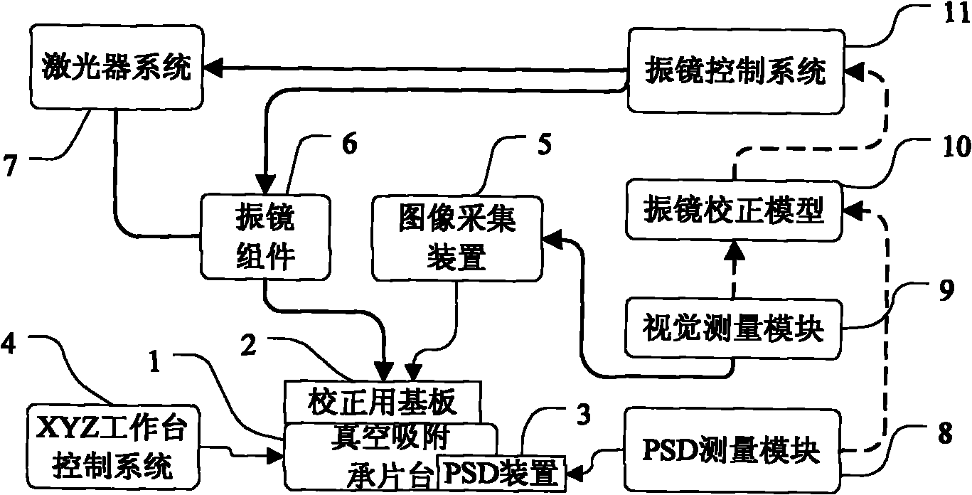
[0031] In this example, if figure 1 As shown, the galvanometer correction device includes:

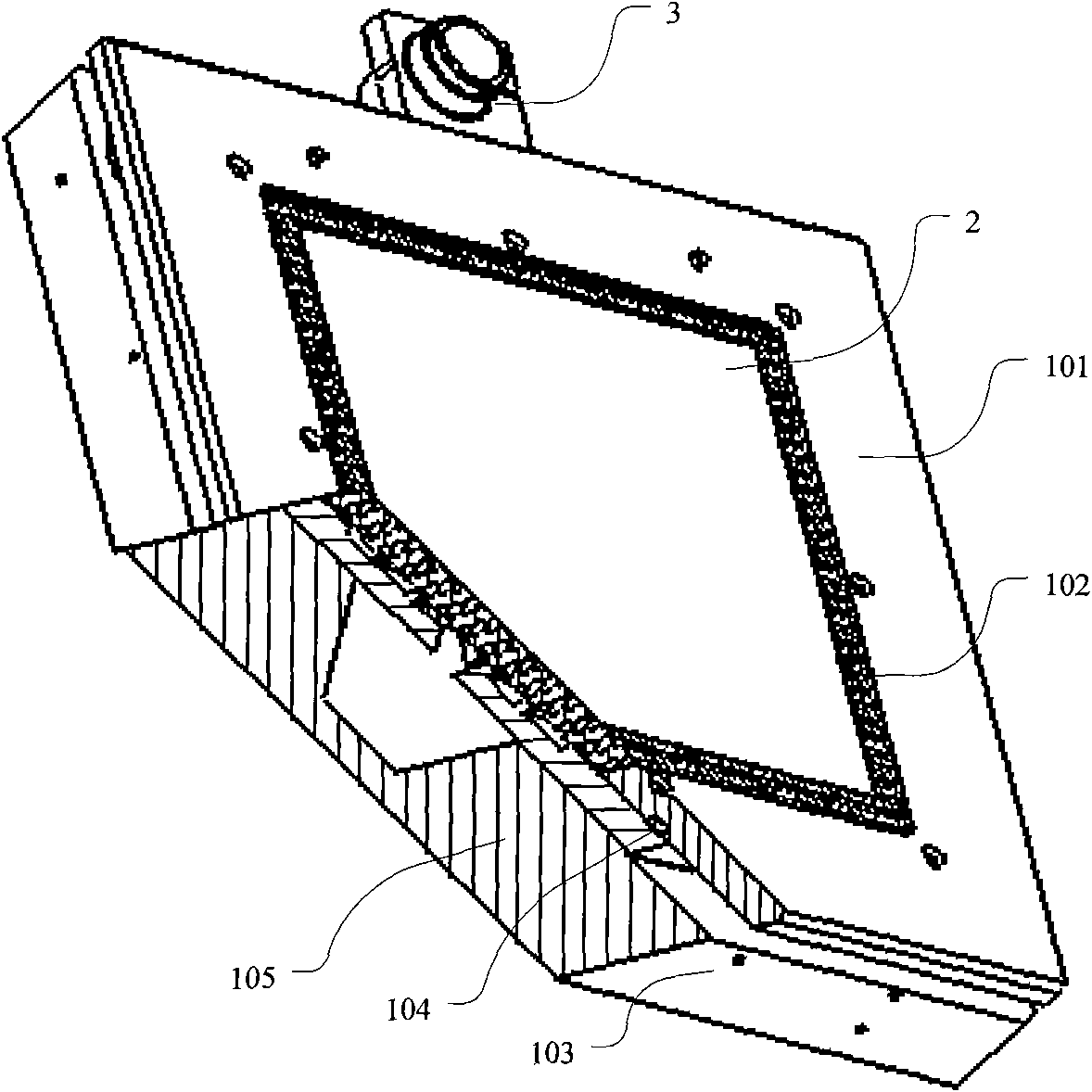
[0032] Vacuum suction wafer stage 1, such as figure 2 As shown, the PSD device 3 is attached thereon, and the adsorption and fixation of the calibration substrate 2 can be completed. The vacuum chamber is formed by the wafer stage base 103, the wafer stage base plate 105, the wafer stage frame 101, the honeycomb board 102 and the polyurethane round belt 104, and the vacuum chamber is connected with the vacuum cleaner through a spring hose; the calibration substrate 2 is placed on the honeycomb board 102. The small residue generated during the processing enters the vacuum cleaner through the core hole on the honeycomb panel 102 , the through hole of the wafer base 105 and the cavity of the wafer base 103 . The polyurethane round b...


PUM


Abstract

The invention provides a galvanometer system correction device and a correction method thereof, and relates to the technical field of precision laser processing equipment. A honeycomb panel is arranged in the middle of the outer frame of a bearing platform, a base plate for corrective is absorbed on the honeycomb panel, and the vacuum chamber of the honeycomb panel is connected with a dust collector; a PSD sensor for measuring the actual output light spot center position of the laser of a galvanometer system is arranged on the vacuum absorption bearing platform; a CCD image acquisition device is arranged above the base plate for correcting, and then is provided with a light intensity regulating module and an image acquisition board card; and a visual measurement algorithm module is arranged. The invention can effectively inhibit the precision drift of the galvanometer system, improve the efficiency of the galvanometer system when in correction model updating and in real-time correction calculation operation, improve the automatic degree of equipment, reduce the labor intensity of an operator, greatly improve the processing precision of equipment, product quality and production efficiency, has simple structure and unique principle and method, and is particularly suitable for precision laser processing equipment to use.

Description

technical field [0001] The invention relates to the technical field of laser precision processing equipment, in particular to a correction device for a vibrating mirror system in laser precision processing equipment. Background technique [0002] At present, laser processing (including laser marking, drilling and cutting, etc.) technology has been widely used in the fields of semiconductor chips, microelectronic circuits and hybrid integrated circuit packaging. Due to the small inertia, extremely fast acceleration and deceleration, and the processing speed can be as high as 12m / s, the galvanometer system is usually integrated into the laser processing equipment as a core component. However, the ever-changing high-density packaging and high-density interconnection technology (HDI) also put forward higher requirements for the accuracy of the whole machine (the accuracy of the whole machine is better than ±15um). Often, the introduction of a galvo system introduces various err...

Claims


Application Information

Patent Timeline
IPC IPC(8): B23K26/42B23K26/70
Inventor 孟凡辉许志伟
Owner THE 45TH RES INST OF CETC
Why Eureka
Try Eureka