Step mechanical speed changer without power transmission interruption during gear shift
A mechanical transmission and power transmission technology, which is applied in mechanical equipment, mechanical control devices, instruments, etc., can solve problems such as poor shifting quality and shocks that are difficult to compensate, and achieve avoiding fuel waste, alleviating torsional vibration and noise, and improving power sexual effect
- Summary
- Abstract
- Description
- Claims
- Application Information
AI Technical Summary
Problems solved by technology
Method used
Image

Examples
Embodiment 1
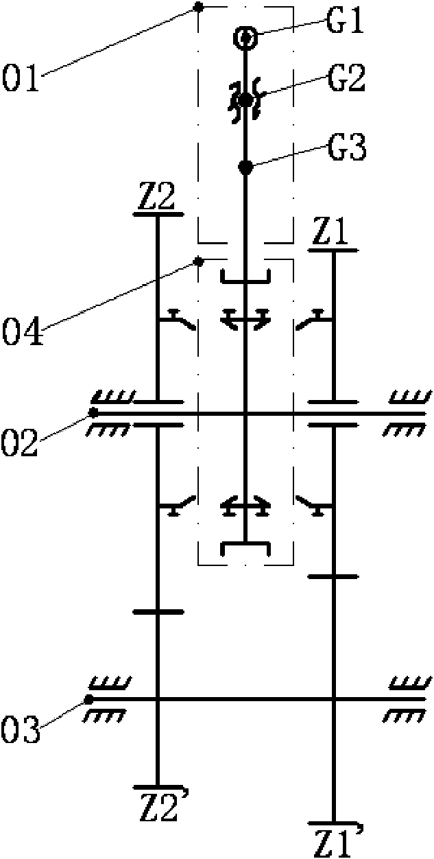
[0051] In this embodiment, the shift combination device of the transmission is shown in Figure 2, and a multi-state controllable clutch with a controllable forced return to neutral device is added to replace the meshing sleeve or synchronizer in a general stepped mechanical transmission.
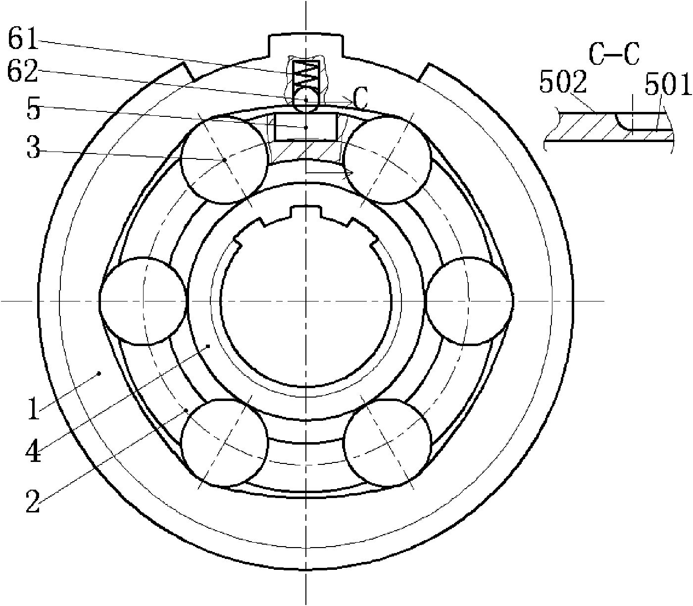
[0052] In Figure 2, the centering spring 62 and the centering steel ball 61 are placed in the radial hole of the outer ring 1; the cage 2 keeps the pitch between the rollers 3 constant, and the inner ring 4 is located in the star wheel shape In the inner cavity, the roller 3 is located in the working space formed by the inner cavity of the outer ring 1 and the outer circle of the inner ring 4; Under the action of the fork ring, not shown in the figure), it can also move axially relative to the outer ring 1 and the cage 2, resulting in the groove 501 or the boss 502 part ( Figure 2a Middle C to sectional view) is in contact with the centering steel ball 61. The outer ring 1 and the inner ri...
Embodiment 2
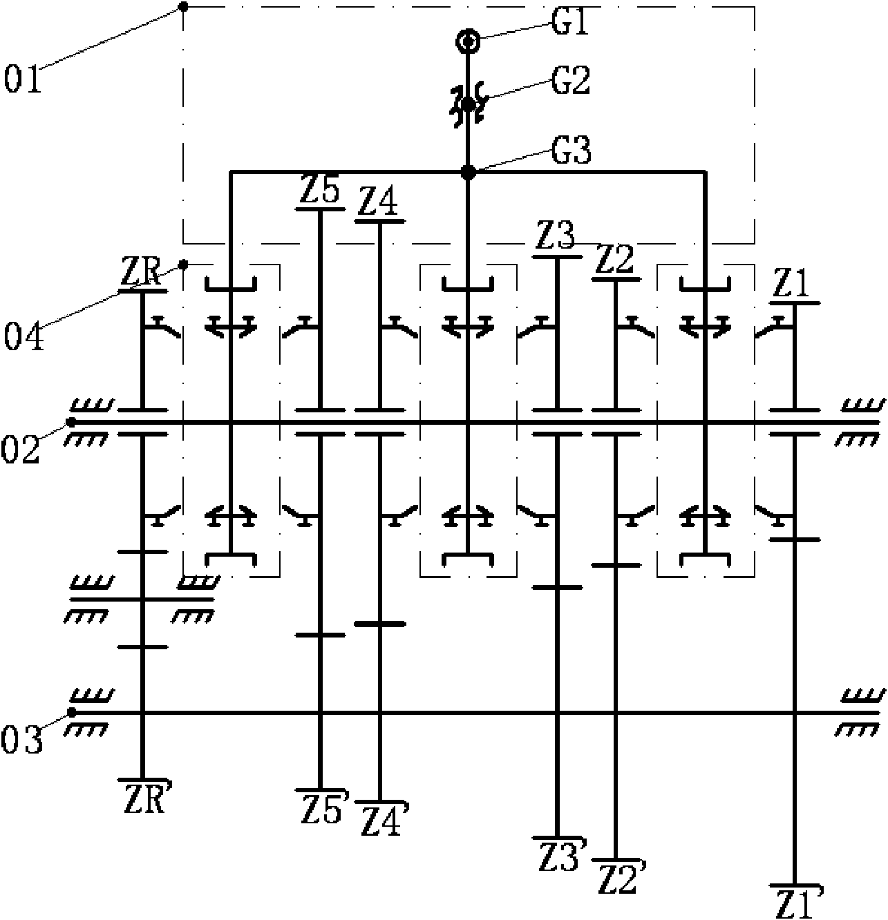
[0071] On the basis that embodiment 1 realizes gear shifting without power interruption between I-II gears, several groups image 3 The shift combination device based on the multi-state controllable clutch shown replaces the synchronizer in the general stepped mechanical manual transmission, as the shift combination device 04 in Fig. A simple change can reliably realize switching between multiple gears without power interruption.
[0072] Such as Figure 6 As shown, the end G3 of the shift lever can move longitudinally and laterally under the control of the shift lever (not shown in the figure); the shift fork shafts 71, 72, 73 are arranged side by side, and there are proper shaped design The shift slot can move laterally under the push of G3 at the end of the shift lever. Both ends of the shift fork shaft are equipped with return springs 621 to ensure that the shift fork shaft returns to the neutral position after breaking away from the constraint of the end of the shift rod...
Embodiment 3
[0080] The multi-state controllable clutch in the present embodiment uses the inner star wheel two-way roller type ( Figure 13 ) or sprag-type free-wheel clutch as a basis for controllable improvement. The biggest difference between it and Embodiment 1 is that it can switch between all the aforementioned four working states under control.
[0081]The structural features of the multi-state controllable clutch of this embodiment differ from that of Embodiment 1 in that first, the inner profile of the outer ring 1 is circular, and the inner ring 2 becomes a star wheel; ) on the extended part of the cage 2', set a number of control windows 25 with appropriate shapes ( Figure 14 ) to cooperate with the finger pin 9, and the finger pin 9 is affixed to the shift fork ring 52 (not shown in the figure).
[0082] Under the constraints of the control window 25, through the forced axial movement of the actuator such as the fork ring, the finger pin 9 makes the cage 2' (thereby the rol...
PUM
 Abstract
Description
Claims
Application Information
 - R&D
- Intellectual Property
- Life Sciences
- Materials
- Tech Scout
- Unparalleled Data Quality
- Higher Quality Content
- 60% Fewer Hallucinations
Browse by: Latest US Patents, China's latest patents, Technical Efficacy Thesaurus, Application Domain, Technology Topic, Popular Technical Reports.
© 2025 PatSnap. All rights reserved.Legal|Privacy policy|Modern Slavery Act Transparency Statement|Sitemap|About US| Contact US: help@patsnap.com