Adjustable-assembly parameter endurance testing device for electromagnetic relay

A technology of electromagnetic relay and life test, applied in circuit breaker test and other directions, can solve the problems of studying the influence of electromagnetic suction and mechanical reaction force on electrical life, and achieve the effect of simple structure and convenient operation.

Inactive Publication Date: 2010-08-18
HARBIN INST OF TECH
View PDF3 Cites 13 Cited by
  • Summary
  • Abstract
  • Description
  • Claims
  • Application Information

AI Technical Summary

Problems solved by technology

[0003] The purpose of the present invention is to solve the problem that the existing electromagnetic relay life testing device cannot study the coordination relationship between electromagnetic attraction force and mechanical reaction force and the influence on electrical life by changing the assembly parameters, and then provides an adjustable assembly parameter Electromagnetic relay life test device

Method used


Image

  • Adjustable-assembly parameter endurance testing device for electromagnetic relay
  • Adjustable-assembly parameter endurance testing device for electromagnetic relay
  • Adjustable-assembly parameter endurance testing device for electromagnetic relay

Examples


specific Embodiment approach 1

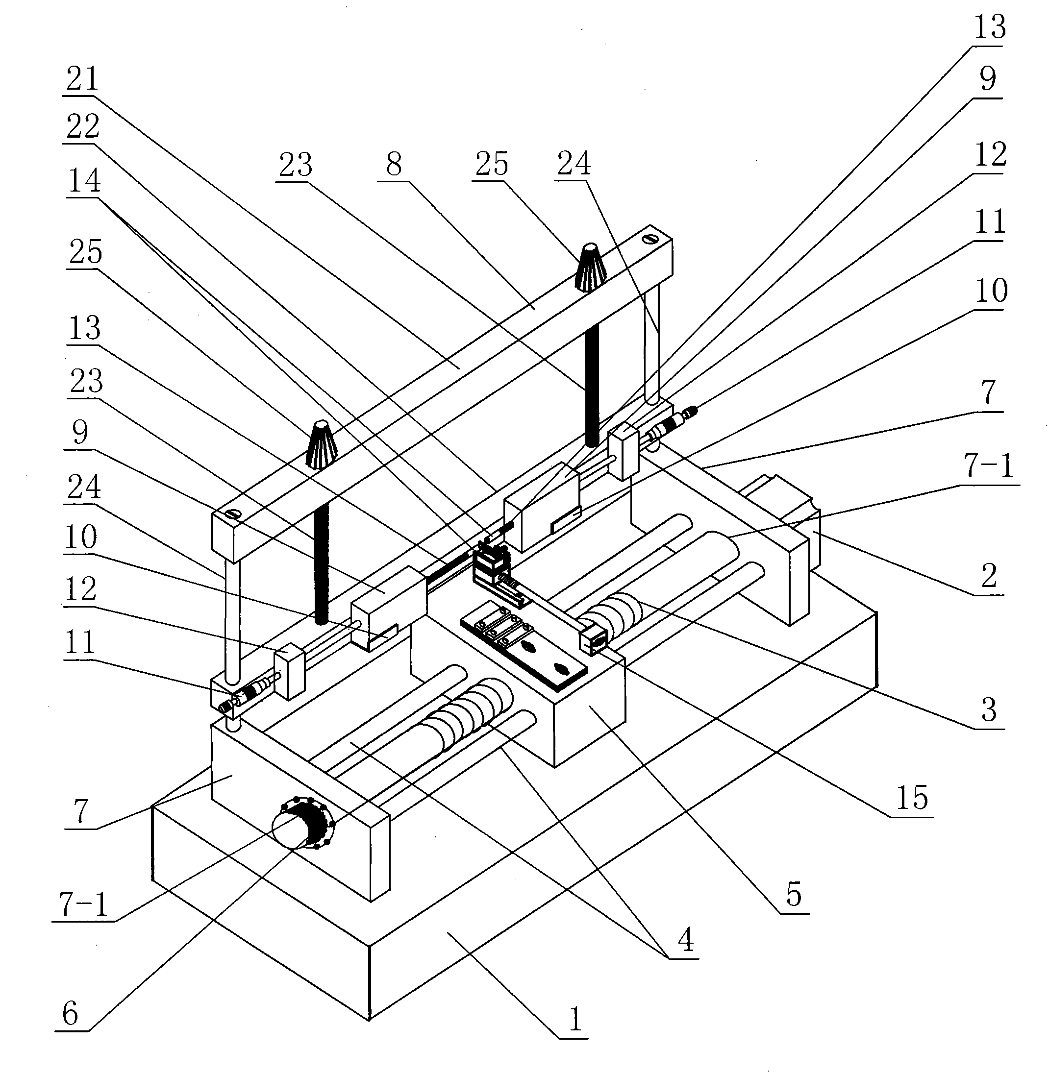
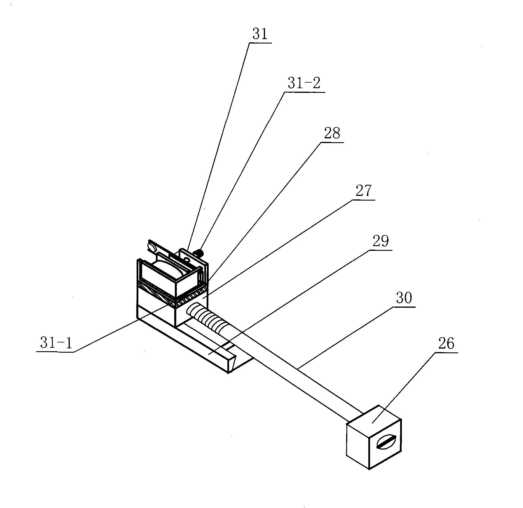
[0007] Specific implementation mode one: as Figure 1~2 As shown, the electromagnetic relay life test device with adjustable assembly parameters in this embodiment consists of a base plate 1, a stepping motor 2, a first lead screw 3, two horizontal guide rails 4, an adjustment block 5, an adjustment knob 6, and two vertical plates 7. Vertical adjustment device 8, two pressure sensors 9, two sensor brackets 10, two differential devices 11, two fixed blocks 12, two insulating rods 13, two static contacts 14 and moving contacts The adjustment device 15 is composed of the two vertical plates 7 that are relatively parallel and fixed on the upper end surface of the bottom plate 1, and the two vertical plates 7 are correspondingly opened with first through holes 7-1, and the first lead screw The two ends of 3 are correspondingly worn in the first through holes 7-1 of the two vertical plates 7 and are connected with the two vertical plates 7 in rotation. The adjustment knob 6 is insta...

specific Embodiment approach 2

[0008] Specific implementation mode two: as figure 1 As shown, the vertical direction adjustment device 8 in this embodiment is composed of a first crossbeam 21, a second crossbeam 22, two second lead screws 23 and two vertical guide rails 24, and the two vertical guide rails 24 The upper ends are affixed to the two ends of the first crossbeam 21 respectively, and the lower ends of the two vertical guide rails 24 pass through the second crossbeam 22 and are affixed to the upper end faces of the corresponding vertical plates 7. The lower ends of the lead screws 23 pass through the first beam 21 and are screwed to the second beam 22 . With such a design, the heights of the two static contacts 14 on the vertical adjustment device 8 can be adjusted. Other components and connections are the same as those in the first embodiment.

specific Embodiment approach 3

[0009] Specific implementation mode three: as figure 1 As shown, the vertical adjustment device 8 in this embodiment further includes two adjustment handles 25 , and one adjustment handle 25 is provided on the upper end of each second lead screw 23 . With such a design, the second lead screw 23 can be rotated conveniently. Other components and connections are the same as those in the second embodiment.


PUM


Abstract

The invention discloses an adjustable-assembly parameter endurance testing device for electromagnetic relays and relates to an endurance testing device for the electromagnetic relays. The invention solves the problem that it is impossible to research the influences of the traditional endurance testing device for the electromagnetic relays on the matching relationship between an electromagnetic attraction force and a mechanical counter force and on the electrical endurance by changing an assembly parameter. Adjusting blocks are arranged on a first screw by threaded connection; the lower end of a vertical adjusting device is fixedly arranged on upper end faces of two vertical plates and is positioned on the same side of the two vertical plates; two fixing blocks are symmetrically arranged on the front side wall of the vertical adjusting device; two sensor supports are symmetrically fixed on the front side wall of the vertical adjusting device and are positioned between the two fixing blocks; and two pressure sensors are positioned on the two sensor supports and are in sliding connection with the sensor supports respectively. The device makes it is possible to research the influences of the device on the matching relationship between the electromagnetic attraction force and the mechanical counter force by changing the assembly parameter and on the electrical endurance of the electromagnetic relays.

Description

technical field [0001] The invention relates to an electromagnetic relay life testing device. Background technique [0002] High reliability and long life are the development direction of electromagnetic relays. However, the arc discharge between the contacts of electromagnetic relays leads to ablation of contact materials, which directly affects the reliability and electrical life of electromagnetic relays. The parameters of electromagnetic relays usually include size parameters, structure parameters and assembly parameters. According to the requirements of pull-in voltage, release voltage, rated voltage, time parameters and contact resistance of the relay, determine the structure of the electromagnetic system, the structure of the contact system and its assembly relationship in the relay. The assembly parameters mainly include the armature stroke, the initial pressure of the static contact, the contact gap, the overtravel of the moving contact, and the magnetic gap. The ...

Claims


Application Information

Patent Timeline
Patent Type & Authority Applications(China)
IPC IPC(8): G01R31/327
Inventor 任万滨翟国富余琼任继成
Owner HARBIN INST OF TECH
Why Eureka
Try Eureka