Fuel cell bi-polar plate with compound sealed structure and manufacturing method thereof

A composite sealing and fuel cell technology, applied in the direction of battery electrodes, structural parts, battery pack parts, etc., can solve the problems of hydrogen leakage, complex assembly, complex process, etc., and achieve the effect of convenient assembly and reliable sealing

Inactive Publication Date: 2010-08-18
KUSN FUERSAI ENERGY
View PDF9 Cites 14 Cited by
  • Summary
  • Abstract
  • Description
  • Claims
  • Application Information

AI Technical Summary

Problems solved by technology

This method is suitable for mass production of sealing gaskets for fuel cells, but the method fails to realize the direct molding of the sealing ring on the pole plate, and the pole plate formed by this method is more complicated in assembly, and must be assembled with a cathode plate, A piece of anode plate and a piece of membrane electrode are stacked in sequence, and a separately formed sealing ring needs to be placed between each unit to seal
This method is not only complicated in process and heavy in workload, but also complicated to disassemble and maintain the stack; and because the sealing ring is originally independent, as shown in Figure 2, the sealing is completely achieved by pressin

Method used


Image

  • Fuel cell bi-polar plate with compound sealed structure and manufacturing method thereof
  • Fuel cell bi-polar plate with compound sealed structure and manufacturing method thereof
  • Fuel cell bi-polar plate with compound sealed structure and manufacturing method thereof

Examples


Embodiment Construction

[0023] The implementation of the present invention will be further described below in conjunction with specific examples. It should be understood that these examples are only used to illustrate the present invention and are not intended to limit the scope of the present invention. In addition, it should be understood that after reading the teachings of the present invention, those skilled in the art can make various changes or modifications to the present invention, and these equivalent forms also fall within the scope defined by the appended claims of the present application.

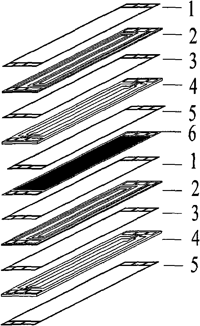
[0024] The fuel cell bipolar plate of the composite sealing structure of the present invention such as image 3 As shown, the cathode plate 4, the anode plate 2, the air flow field seal 14, the water flow field seal 13, and the hydrogen flow field seal 10 are composed. Wherein, the cathode plate 4 has an air flow field 16 and an air flow field sealing groove 15 on one surface, and a water flow field 1...


PUM


Abstract

The invention relates to a fuel cell bi-polar plate with a compound sealed structure and a manufacturing method thereof. An air flow-field sealing element and a hydrogen flow-field sealing element are directly solidified and formed on seal groove surfaces of a cathode plate and an anode plate; a water flow-field sealing element is adhered with the cathode plate and the anode plate into an integer to form the bi-polar plate with the compound sealed structure; and the air flow-field sealing element, the water flow-field sealing element and the hydrogen flow-field sealing element are solidified to be formed on the surfaces of the cathode plate and the anode plate so as to form a molecule binding force sealing layer. The manufacturing method comprises the following steps of: completely processing a boundary dimension, a fluid passage and a fluid distribution passage to obtain the cathode plate and the anode plate by using graphite or metal as forming materials; processing an elastic sealing structure with a retardant function through a sealant coating process in an air seal groove and a hydrogen seal groove of the cathode plate and the anode plate by using a high-temperature solidifying sealant; then carrying out high-temperature solidification to obtain a single-polar plate with the compound sealed structure, and coating the sealant in a water flow-field seal groove of the single-polar plate with the compound sealed structure; and then manufacturing the fuel cell bi-polar plate with the compound sealed structure by pressing the cathode plate and the anode plate to carry out solidification through a press mould.

Description

technical field [0001] The invention relates to a fuel cell and a manufacturing method thereof, in particular to a fuel cell bipolar plate with an integral composite sealed structure and a manufacturing method thereof. Background technique [0002] With the rapid development of science and technology and the continuous improvement of people's living standards, correspondingly, traditional fossil energy (such as oil, natural gas, etc.) has become increasingly unable to meet the needs of human daily production and life. As we all know, traditional energy is mostly non-renewable energy, which will be exhausted sooner or later, and this kind of energy will cause serious global environmental pollution problems. For the sustainable development of the earth and human society, all countries in the world are committed to finding a renewable clean energy. At present, scientists agree that "hydrogen energy" is one of the effective and clean energy sources to replace traditional energy...

Claims


Application Information

Patent Timeline
IPC IPC(8): H01M4/86H01M4/88H01M2/08
CPCY02E60/50
Inventor 徐麟沈军陈捷张超章波陈凌云
Owner KUSN FUERSAI ENERGY
Why Eureka
Try Eureka