
Main device for Ethernet system and relevant clock synchronization method thereof

A network system and clock synchronization technology, which is applied in transmission systems, synchronization devices, digital transmission systems, etc., can solve the problems of unable to adjust the clock phase of transmitted data, clock drift, unable to synchronize clocks, etc.

Active Publication Date: 2010-08-18
REALTEK SEMICON CORP
View PDF0 Cites 3 Cited by
  • Summary
  • Abstract
  • Description
  • Claims
  • Application Information

AI Technical Summary

Problems solved by technology

In this mode, because the slave device does not receive the signal transmitted by the master device, it cannot perform clock recovery.
After a period of time, the clock that sent the signal from the slave device could not perform clock recovery because it did not receive the free-action clock from the master device's transmitting end, resulting in clock drift. When the master device wakes up and needs to transmit the first data, the master device's transmitter cannot know. How much the phase shift of the clock received by the receiver from the signal sent by the device during this period
Therefore, the master cannot adjust the clock of the transmitted data to correspond to the phase drift of the received data
[0006] In short, under the conventional asymmetric mechanism, the master device will not be able to synchronize with the clock of the slave device after waking up because it enters the quiet mode for a period of time. Error in receiving data from the device

Method used


Image

  • Main device for Ethernet system and relevant clock synchronization method thereof
  • Main device for Ethernet system and relevant clock synchronization method thereof
  • Main device for Ethernet system and relevant clock synchronization method thereof

Examples


Embodiment Construction

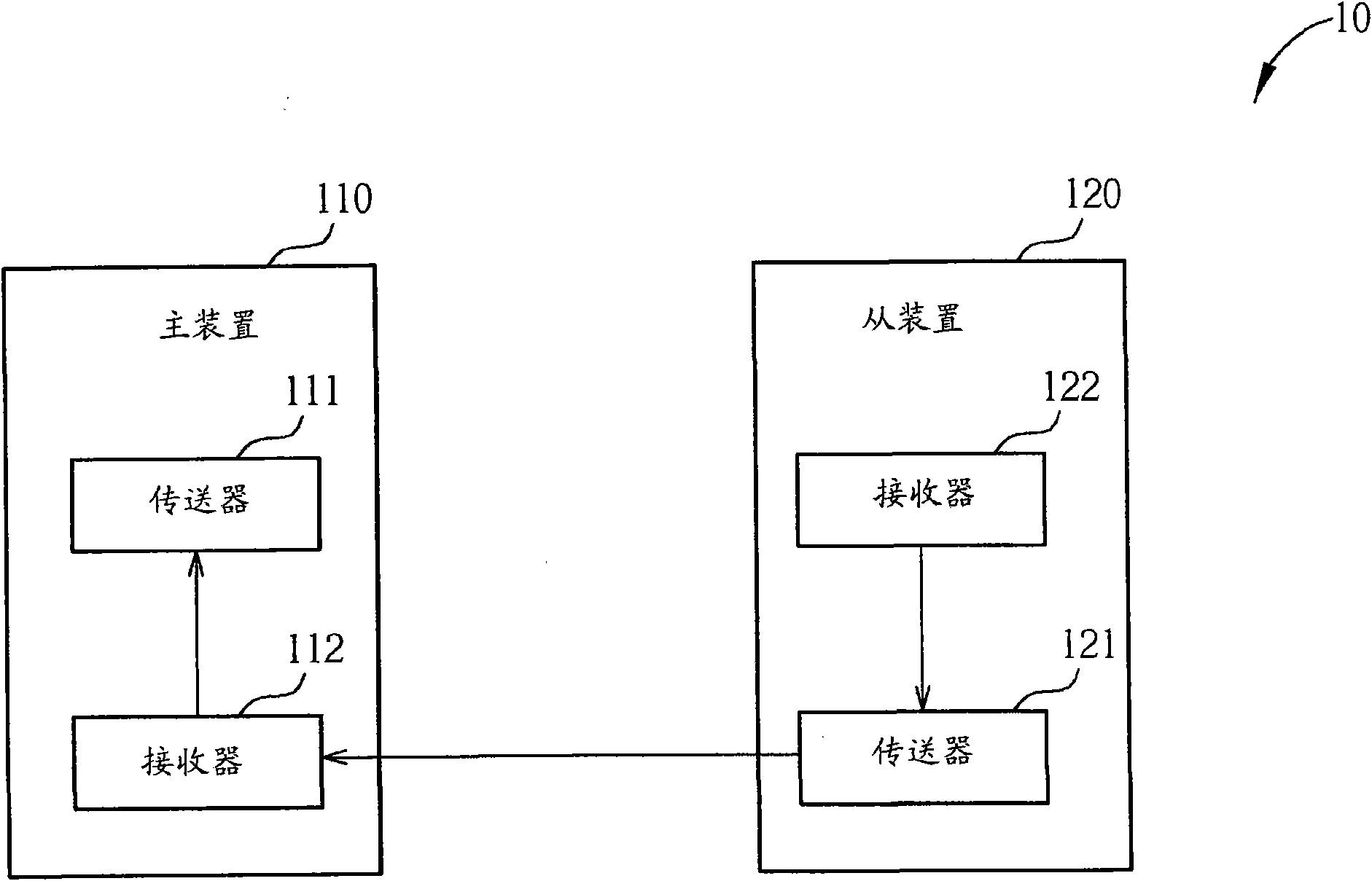
[0044] Please refer to figure 1 , figure 1 It is a schematic diagram of implementing an Ethernet system 10 according to the present invention. The Ethernet system 10 is a Gigabit Ethernet network operating under an asymmetric mechanism. The Ethernet system 10 includes a master device 110 and a slave device 120 . The master device 110 includes a transmitter 111 for transmitting signals, and a receiver 112 for receiving signals from the slave device 120 . The slave device 120 includes a transmitter 121 for transmitting signals to the receiver 112 of the master device 110, and a receiver 122 for receiving signals. When the master device 110 and the slave device perform data transmission, the clock synchronization relationship between the two must be maintained so that the phase state of the receiver at the time of sampling is optimal. That is to say, the clock phases between the master device and the slave device must be the same or maintain a fixed phase difference.

[0045...


PUM


Abstract

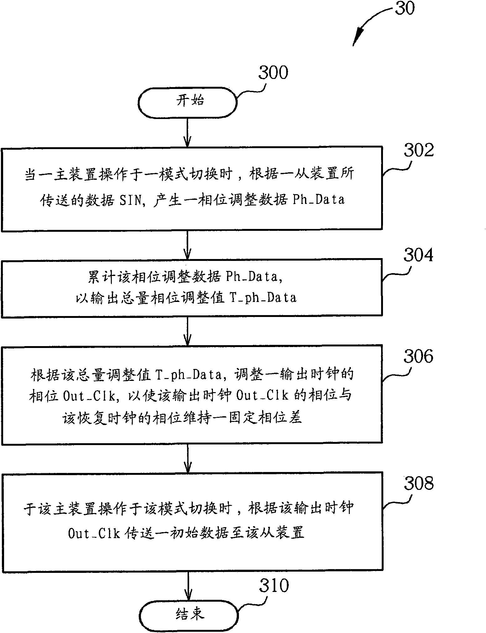
The invention relates to a main device for an Ethernet system, which contains a receiver, a register, a phase locked loop unit and a transmitter, wherein the receiver is used for generating phase adjustment data according to data transmitted by an assistant device, and the data transmitted by the assistant device contains the phase information of a recovery clock of the assistant device; the register is coupled to the receiver and is used for adding up the phase adjustment data so as to output a phase adjustment value; the phase locked loop unit is coupled to the register and is used for adjusting the phase of an output clock according to the phase adjustment value so as to enable the phase of the output clock and the phase of the recovery clock to maintain a fixed phase difference; and the transmitter is used for transmitting initial data to the assistant device according to the output clock when the main device is revived from a silent mode.

Description

technical field [0001] The present invention relates to a main device and its related clock synchronization method, in particular to a main device and its related clock synchronization method used in an Ethernet system. Background technique [0002] In a Giga Ethernet system, whether there is data transmission or not, the master device (Master) and the slave device (Slave) must maintain clock synchronization by transmitting an idle sequence (Idle Sequence). However, continuously transmitting the idle sequence in the absence of data transmission results in excessive power consumption. Therefore, the Institute of Electrical and Electronics Engineers (IEEE) has formulated the specification of Energy Efficient Ethernet (EEE) to save power consumption. Under the Energy Efficiency Ethernet specification, when the master and slave devices are not transmitting data, both devices enter sleep mode, only occasionally waking up to transmit idle sequences to maintain synchronization. ...

Claims


Application Information

Patent Timeline
Patent Type & Authority Applications(China)
IPC IPC(8): H04L7/033
Inventor 俞丁发黄亮维张荣仁李明哲
Owner REALTEK SEMICON CORP
Learn More