
Heat dissipation method for friction surface of wet clutch of automobile gear box

A technology for wet clutches and automotive gearboxes, applied in clutches, friction clutches, mechanical drive clutches, etc., can solve problems affecting clutch durability, limiting clutch heat capacity, and torque transmission, etc., to enhance momentum and energy exchange and improve mixing , Increase the effect of heat transfer temperature difference

Active Publication Date: 2012-10-03
安徽易佳斯动力科技有限公司
View PDF0 Cites 0 Cited by
  • Summary
  • Abstract
  • Description
  • Claims
  • Application Information

AI Technical Summary

Problems solved by technology

Therefore, in the above-mentioned common oil tank design, the temperature gradient increases with the radius of the oil tank (inner diameter to outer diameter), so the highest temperature usually occurs at the outer diameter of the friction surface, which limits the heat capacity of the clutch and the transmission of torque, which greatly affects the clutch. Durability, Reliability and Efficiency

Method used


Image

  • Heat dissipation method for friction surface of wet clutch of automobile gear box
  • Heat dissipation method for friction surface of wet clutch of automobile gear box
  • Heat dissipation method for friction surface of wet clutch of automobile gear box

Examples


Embodiment Construction

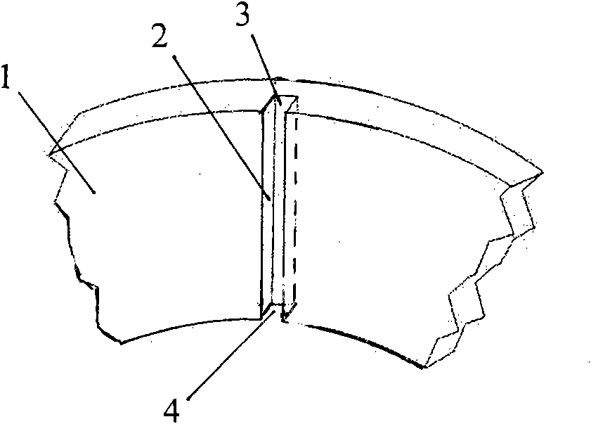
[0017] Figure 1 ~ Figure 4 The cooling oil sump shown is taken from a section of the automatic transmission lockup clutch annular plates. figure 1 It is a schematic diagram of the structure of the cooling oil groove in the prior art. The cooling oil groove 2 is radial and straight, and the highest temperature usually occurs on the outer diameter of the friction surface, and the heat dissipation effect is not good.

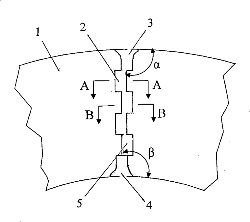
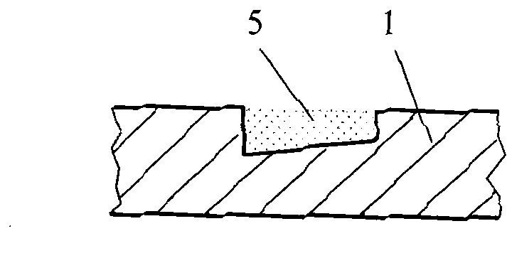
[0018] Figure 2 ~ Figure 4 It is a schematic diagram showing the direction of the structure of the cooling oil tank and the cross-sectional shape of the grid-shaped oil tank in the present invention. As can be seen from the figure, a heat dissipation method for the friction surface of a wet clutch of an automobile gearbox is characterized in that the cooling oil flows from the oil inlet 3 on the outer diameter of the driven disc to the oil outlet 4 on the inner diameter of the driven disc through the cooling oil groove 2 and flows out , the cooling oil flows in...


PUM


Abstract

The invention discloses a heat dissipation method for a friction surface of a wet clutch of an automobile gear box. The heat dissipation method is characterized in that cooling oil flows in through a flow-in port along the external diameter of a driven disk and then flows out from an oil flow-out port along the internal diameter of the driven disk through a cooling oil tank; the cooling oil rollsand flows in the cooling oil tank to be mixed fully so as to dissipate heat; the cooling water tank consists of a plurality of grid-shaped oil tanks connected in series; the grid-shaped oil tanks arealternately arranged with higher left and lower right or with lower left and higher right in an interlocking way along the radial direction; and the radial direction refers to the radius direction ofthe driven disk. The method has the advantages that: strong partial turbulent flow is produced in a shear layer of the oil flow at the connecting necking of two adjacent grid-shaped oil tanks so as to enhance the momentum exchange and the energy exchange of the oil flow; the reverse sliding of a driving disk and the driven disk on the friction surface produces the annular flow vertical to the flowing direction of the oil tank, so that the oil at a lower temperature constantly rolls to the friction boundary so as to increase the heat transfer temperature difference; and the high and low alternate arrangement of the cooling oil tanks and the depth variation roll the oil flow and enhance the pulsation of the main flow so as to improve the heat transfer effect.

Description

technical field [0001] The invention belongs to the technical field of automobile gearboxes, and relates to a heat dissipation method for a friction surface when a wet clutch is closed. Background technique [0002] The wet clutch is a device widely used in automobile gearboxes to transmit and cut off torque. It consists of a steel driving disc on the engine side and a driven disc on the output shaft side of the gearbox. The driven disc has a friction lining. Under the working conditions such as starting on a slope, maintaining on a slope, and introducing friction to improve shifting quality, the excessive temperature rise caused by the relative friction between the driving disc and the driven disc will cause the friction material to advance With aging, the cooling oil decomposes, which eventually leads to a decrease in cooling effect and failure of the clutch. Therefore, cooling of the clutch friction surfaces is critical to both its performance and long-term durability. ...

Claims


Application Information

Patent Timeline
Patent Type & Authority Patents(China)
IPC IPC(8): F16D13/72
Inventor 袁一卿陶伟杜国平张铭吕康
Owner 安徽易佳斯动力科技有限公司
Learn More