Liquid heating device, core of the the device and a fabricating method thereof

一种加热装置、部件的技术,应用在流体加热器、水加热器、照明和加热设备等方向,能够解决易毁坏、易形成裂痕、毁坏电路等问题,达到省却电子控温、热传率促进、高热传系数的效果

Inactive Publication Date: 2012-10-17
TOPMASTER IN TECH
View PDF0 Cites 0 Cited by
  • Summary
  • Abstract
  • Description
  • Claims
  • Application Information

AI Technical Summary

Problems solved by technology

When this happens, based on the heat gap, the core component will be subjected to a huge heat stress, and cracks will easily form after a long period of use
When cracks are formed in the core components, the heating element will inevitably be affected and even easily destroyed
In addition, the circuit is usually located on the other side of the heating component, and a crack in the core component will also destroy the circuit
Likewise, with common liquid heaters, when no or not enough water originates in the core components, the heating element can easily overheat and be destroyed
To solve this problem, some common liquid heaters are equipped with a complex electronic temperature control to monitor and limit the maximum heating temperature
However, these circuits often fail to click on the problem properly and often create other new problems
Among other things, these circuits can be very expensive and need to add to the production cost

Method used


Image

  • Liquid heating device, core of the the device and a fabricating method thereof
  • Liquid heating device, core of the the device and a fabricating method thereof
  • Liquid heating device, core of the the device and a fabricating method thereof

Examples


Embodiment 1

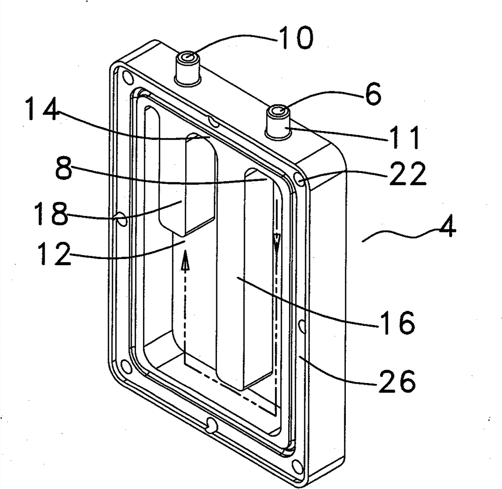
[0051] Attached Figure 1 to Figure 6 , Is a specific embodiment of a liquid heating device (such as a drinking water heating device). As attached figure 1 As shown, the liquid heating device is usually labeled 2. Two joining positions 11 are attached to the top of the liquid heating device 2.

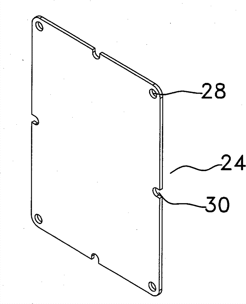
[0052] figure 2 It is an exploded view of the main parts of the liquid heating device. The liquid heating device 2 includes a core component 4 in the middle part of the device 2. The core part 4 provides a liquid inlet part 6 named as the first channel 8 through which the liquid is introduced into the core part 4. The core component 4 also provides a liquid outlet component 10 named as the second channel 12, through which the heated liquid leaves the core component 4. image 3 Independently show the core components 4 more clearly. Refer to Figure 1 to Figure 3 , The water inlet part 6 and the water outlet part 10 are adapted to each other with the joint position 11. The core compone...

Embodiment 2

[0062] The difference between the second embodiment and the first embodiment is that the liquid heating device 2 adopts a core component 40 with a different structure in the second embodiment. As attached Figure 7 As shown, here is shown a clearer or narrower channel 42 attached to the core component 40, and the main part of the channel 42 is arranged in parallel with the direction of the water inlet or outlet. It can be understood here that when comparing the core component 4 in the first embodiment, this core component 40 has a relatively large inner surface area, so that the water source tends to contact the surface of the channel 42 when it flows through, which can increase heat transfer to The efficiency of the liquid.

Embodiment 3

[0064] Figure 8a , 8b and 8c disclose other three different core components 44, 46 and 48, and their common point is that the water inlet and outlet components are both arranged on top of the core component. When they are all rotated 90 degrees clockwise, it can be considered that the water inlet part and the water outlet part are arranged on the side of the core part, and the water outlet part is arranged above the water inlet part. One of the features of the core component 44 is that the water inlet component 50 and the corresponding passage 52 are lower than the water outlet component 56 and the corresponding passage 54. Similarly, the core component 44 supplies a temporary storage assembly 58 or storage on the other side of the channel 52. The temporary storage component 58 can be used to temporarily store vapor or vaporized water in the core component 44 so that the vapor does not easily flow out of the core component 44. This can reduce the amount of steam discharged fr...


PUM


Abstract

This invention discloses a liquid heating device, core of the said device and a fabricating method thereof. Said liquid heating device includes: a core arranged a channel for flowing the liquid inside it and attached a water inlet level and a water outlet level; at least a thermal diffusion part having a first face and a second face. Said thermal diffusion part is fixed in the center of the coreand the first face is jointed with the core; at least a heating components fixed on the thermal diffusion part and jointed with the second face of the thermal diffusion part, either the heating components or the thermal diffusion part acts as a independent part or formed a whole inseparable body with the core; a case for strengthening purpose. The advantage of this invention is that an even heating process can reduce the risk of overheating of the heating components. Said thermal diffusion part can protect heating components from overheating when there is not enough liquid in core, in addition, promoting the liquid to be discharged easily and at the same time, increasing the heat transfer efficiency from the heating components to the liquid in the core.

Description

Technical field [0001] The invention relates to a liquid heating device, in particular to a liquid heating device used in an automatic drinking fountain or a beverage diverter, a core component of the liquid heating device and a manufacturing method of the liquid heating device. technical background [0002] There are different liquid heating devices on the market. Each liquid heating device has a different design to meet the needs of different users. For example, one of the basic requirements is a commercial drinking water heater for hotels. This purpose requires that a large amount of hot water can be provided to multiple hotel rooms at the same time without hindrance. Based on this demand, the liquid heater of the hotel is usually equipped with a water storage tank to store and maintain a relatively large amount of hot water to cater for consumption by hotel guests. Therefore, the supply of hot water to cater to the needs of multiple guests is the priority, and the supply of...

Claims


Application Information

Patent Timeline
Patent Type & Authority Patents(China)
IPC IPC(8): F24H1/00F24H9/00F24H9/18
Inventor 陈永辉陈永坚
Owner TOPMASTER IN TECH
Why Eureka
Try Eureka