
Low-side driving circuit for vehicle-mounted relay

A low-side drive and relay technology, applied in relays, circuits, electrical components, etc., can solve the problems of overheating of the coil, inability to pull in at high temperature and low voltage, smaller coil current, and poor heat dissipation.

Pending Publication Date: 2021-09-14
UNITED AUTOMOTIVE ELECTRONICS SYST
View PDF12 Cites 0 Cited by
  • Summary
  • Abstract
  • Description
  • Claims
  • Application Information

AI Technical Summary

Problems solved by technology

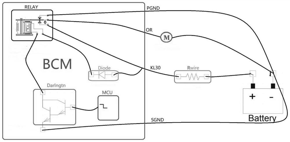
[0007] 2. Under the condition of high temperature (85°C) and low voltage (9V), due to the existence of the forward voltage of the reverse protection diode (Diode) and the voltage of the Darlington transistor (Darlngtn), the resistance value of the coil increases with the temperature. However, the larger impact will cause the coil current to become smaller, and there is a risk that the contacts will not be able to pull in
In order to meet the pull-in current, the vehicle-mounted relays have increased the pull-in voltage value. At the same time, due to the reduction of the package, the heat dissipation has deteriorated, so the risk of coil overheating and high temperature and low voltage failure to pull in is bound to increase.

Method used


Image

  • Low-side driving circuit for vehicle-mounted relay
  • Low-side driving circuit for vehicle-mounted relay
  • Low-side driving circuit for vehicle-mounted relay

Examples


Embodiment Construction

[0046] A preferred embodiment will be given below, and the present invention will be described more clearly and completely in conjunction with the accompanying drawings.

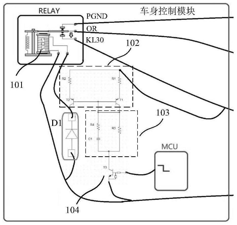
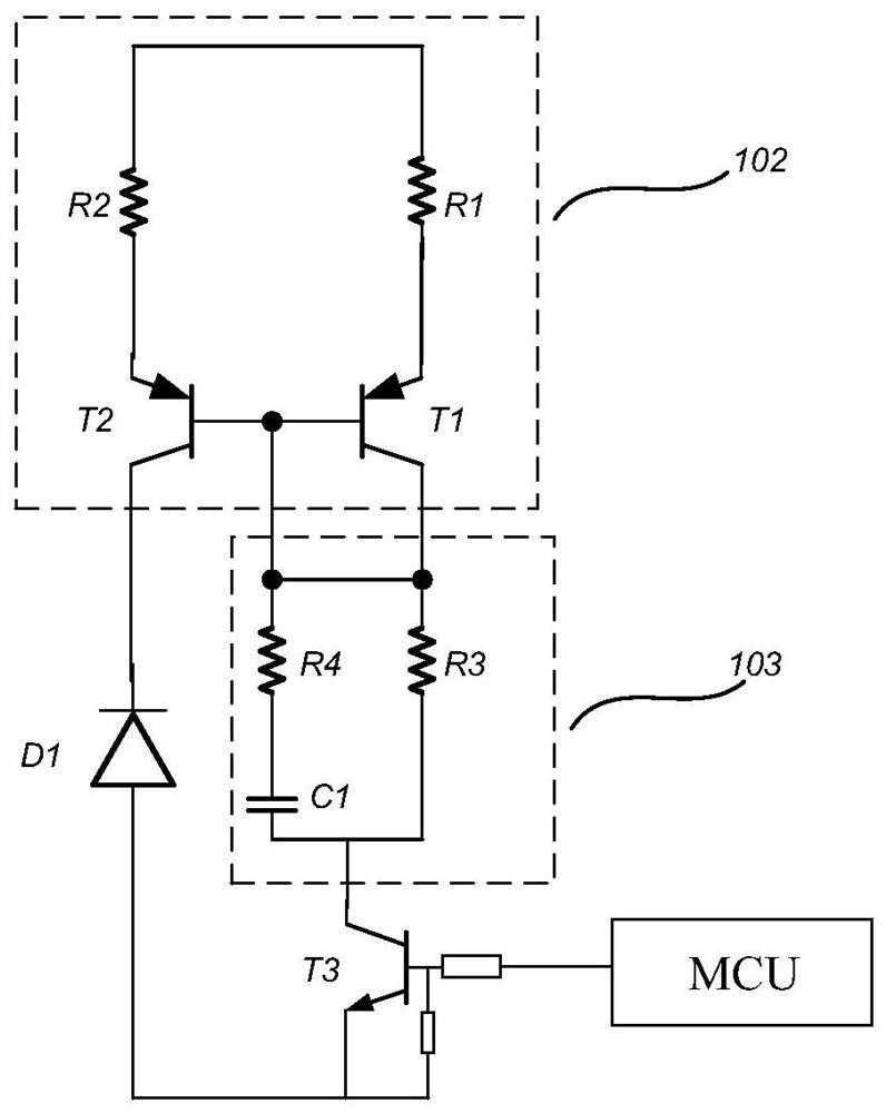
[0047] This embodiment provides a low-side drive circuit for a vehicle-mounted relay. refer to figure 2 , image 3 The vehicle-mounted relay low-side drive circuit includes a relay RELAY, a triode mirror circuit 102, a time-varying resistance circuit 103, a diode D1, a controllable switch 104, and a main control unit.

[0048] The relay RELAY includes an armature OR, a normally open contact KL30, a normally closed contact PGND, and a coil 101; the triode mirror circuit 102 includes an input terminal, a first output terminal, and a second output terminal; the input terminal is electrically connected to the normally open contact KL30, The first output end, the cathode of the diode are electrically connected to one end of the coil 101; one end of the time-varying resistance circuit 103 is electrically connec...


PUM


Abstract

The invention provides a low-side driving circuit of a vehicle-mounted relay. The circuit comprises a relay, a triode mirror image circuit, a time-varying resistance circuit, a diode, a controllable switch and a main control unit; the relay comprises a normally open contact and a coil; the triode mirror image circuit comprises an input end, a first output end and a second output end; the input end is electrically connected with the normally open contact, and the first output end and the cathode of the diode are electrically connected with one end of the coil; one end of the time-varying resistance circuit is electrically connected with the second output end; the controllable switch comprises a first end, a second end and a control end; the first end is electrically connected with the other end of the time-varying resistance circuit, and the second end and the anode of the diode are electrically connected with the other end of the coil; and the main control unit is electrically connected with the control end. According to the low-side driving circuit for the vehicle-mounted relay, the triode mirror image circuit is used for forming a current negative feedback circuit, the amplitude of relay coil current rising along with voltage is reduced, and the coil overheating risk is reduced.

Description

technical field [0001] The invention relates to the technical field of vehicle body control, in particular to a low-side drive circuit for a vehicle-mounted relay. Background technique [0002] Electromagnetic relay has been widely used as an electronic control device. It consists of a control system (iron core, coil, reed) and a controlled system (armature, normally open contact, normally closed contact, reed contact), and has the function of controlling a larger current with a smaller current . As long as a certain voltage is applied to both ends of the coil, a certain current will flow through the coil, thereby generating an electromagnetic effect. The moving contact and the static contact (normally open contact) are sucked together. Whether or not the contacts close usually depends on the current flowing through the relay coil. In the automotive field, on-board relays (electromagnetic relays) are widely used in body control modules to drive motors such as doors and w...

Claims


Application Information

Patent Timeline
IPC IPC(8): H01H47/32
CPCH01H47/325
Inventor 魏庆忠邹素瑞熊磊周涛王乐
Owner UNITED AUTOMOTIVE ELECTRONICS SYST
Learn More