Composite optical eddy generation method and device thereof
A method of generating optical vortices, applied in optical recording/reproducing/erasing methods, recording/reproducing/erasing using optical interference patterns, radiation/particle processing, etc., can solve the difficulties and difficulties of parallelism and coaxiality Large and other problems, to achieve the effects of variety, simple production process, and increased storage capacity
- Summary
- Abstract
- Description
- Claims
- Application Information
AI Technical Summary
Problems solved by technology
Method used
Image
Examples
Embodiment 1
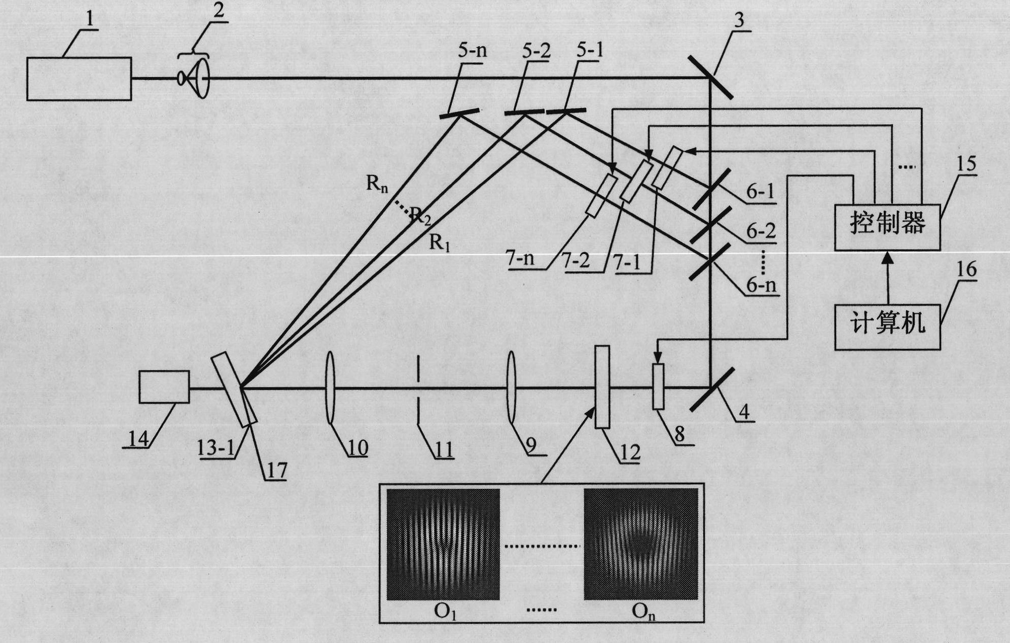
[0037]Please refer to Fig. 2, which is the main optical path structure of the first embodiment of the method for producing a composite optical vortex proposed by the present invention, including a laser light source 1, a beam expander 2, a second beam expander, and A reflecting mirror 3, beam splitter 6-1, by being arranged on the first reference light path shutter 7-1 and reference light path reflector 5-1 on this beam splitter 6-1 reflected light path; 1 the beam splitter 6-2 on the transmitted light path and the second reference light path shutter 7-2 and the reference light path reflector 5-2 on the reflected light path; ...; the nth on the reflected light path of the beam splitter 6-n A reference light path shutter 7-n and a reference light path reflector 5-n, the second reflector 4 on the transmission light path of the beam splitter 6-n, the main shutter 8, the vortex plane holographic generator 12, the first Fourier A leaf transform lens 9 , a first pinhole filter 11 , ...
Embodiment 2
[0047] Please refer to FIG. 4 , which is the main optical path structure of the second embodiment of the method for producing a composite optical vortex proposed by the present invention, including a laser light source 1, a beam expander 2, a second beam expander, and a second optical path arranged on the outgoing light path of the laser light source 1 in sequence. A reflecting mirror 3, beam splitter 6-1, by being arranged on the first reference light path shutter 7-1 and reference light path reflector 5-1 on this beam splitter 6-1 reflected light path; 1 the beam splitter 6-2 on the transmitted light path and the second reference light path shutter 7-2 and the reference light path reflector 5-2 on the reflected light path; ...; the second on the reflected light path of the beam splitter 6-n n reference light path shutters 7-n and reference light path reflectors 5-n, the second reflector 4, the main shutter 8, the spiral phase plate vortex generator 18 on the transmission ligh...
Embodiment 3
[0051] Please refer to FIG. 5 , which is the main optical path structure of the third embodiment of the method for generating a compound optical vortex proposed by the present invention, including a laser light source 1, a beam expander 2, a second beam expander, and A reflecting mirror 3, beam splitter 6-1, by being arranged on the first reference light path shutter 7-1 and reference light path reflector 5-1 on this beam splitter 6-1 reflected light path; 1 the beam splitter 6-2 on the transmitted light path and the second reference light path shutter 7-2 and the reference light path reflector 5-2 on the reflected light path; ...; the nth on the reflected light path of the beam splitter 6-n A reference light path shutter 7-n and a reference light path reflector 5-n, a second reflector 4, a main shutter 8, a mode conversion vortex generator 19 on the beam splitter 6-n transmission light path, a reference light path reflector 5 The direction of the vortex is set so that the ref...
PUM
 Abstract
Description
Claims
Application Information
 - R&D
- Intellectual Property
- Life Sciences
- Materials
- Tech Scout
- Unparalleled Data Quality
- Higher Quality Content
- 60% Fewer Hallucinations
Browse by: Latest US Patents, China's latest patents, Technical Efficacy Thesaurus, Application Domain, Technology Topic, Popular Technical Reports.
© 2025 PatSnap. All rights reserved.Legal|Privacy policy|Modern Slavery Act Transparency Statement|Sitemap|About US| Contact US: help@patsnap.com


