
Umbilic clamping cutter

A cutter and umbilical cord technology, applied in the field of medical equipment, can solve the problems of not being able to adjust the cutting length of the umbilical cord in time, the emergency treatment, the unclear position of the umbilical wheel and the cutting process of the umbilical cord, and threats to the physical and mental health of medical staff. The effect of splashing, avoiding the risk of infection, and the umbilical cord falling off quickly

Active Publication Date: 2010-09-01
宁波菲特医疗器械有限公司
View PDF9 Cites 16 Cited by
  • Summary
  • Abstract
  • Description
  • Claims
  • Application Information

AI Technical Summary

Problems solved by technology

[0003] But this clamping and cutting device has a great defect in the use and operation process, that is, when operating, the hands of the medical staff always hold the clamper Both clamps and clamps are covered in the palm of the hand, which is not only inconvenient to operate, but also the umbilical wheel and the entire cutting process of the umbilical cord can not be seen clearly from the outside, let alone the cutting length of the umbilical cord can be adjusted in time and emergency treatment can be performed.
[0004]In addition, it clamps the umbilical cord with two clamps while pushing the clamps and the umbilical cord to move toward the blade on the clamper for cutting, so when cutting The blood splatter in the umbilical cord is serious. If you encounter AIDS or sexually transmitted diseases, the splattered blood will seriously threaten the physical and mental health of medical staff

Method used


Image

  • Umbilic clamping cutter
  • Umbilic clamping cutter
  • Umbilic clamping cutter

Examples


Embodiment Construction

[0014] Embodiments of the present invention will be further described in detail below in conjunction with the accompanying drawings.

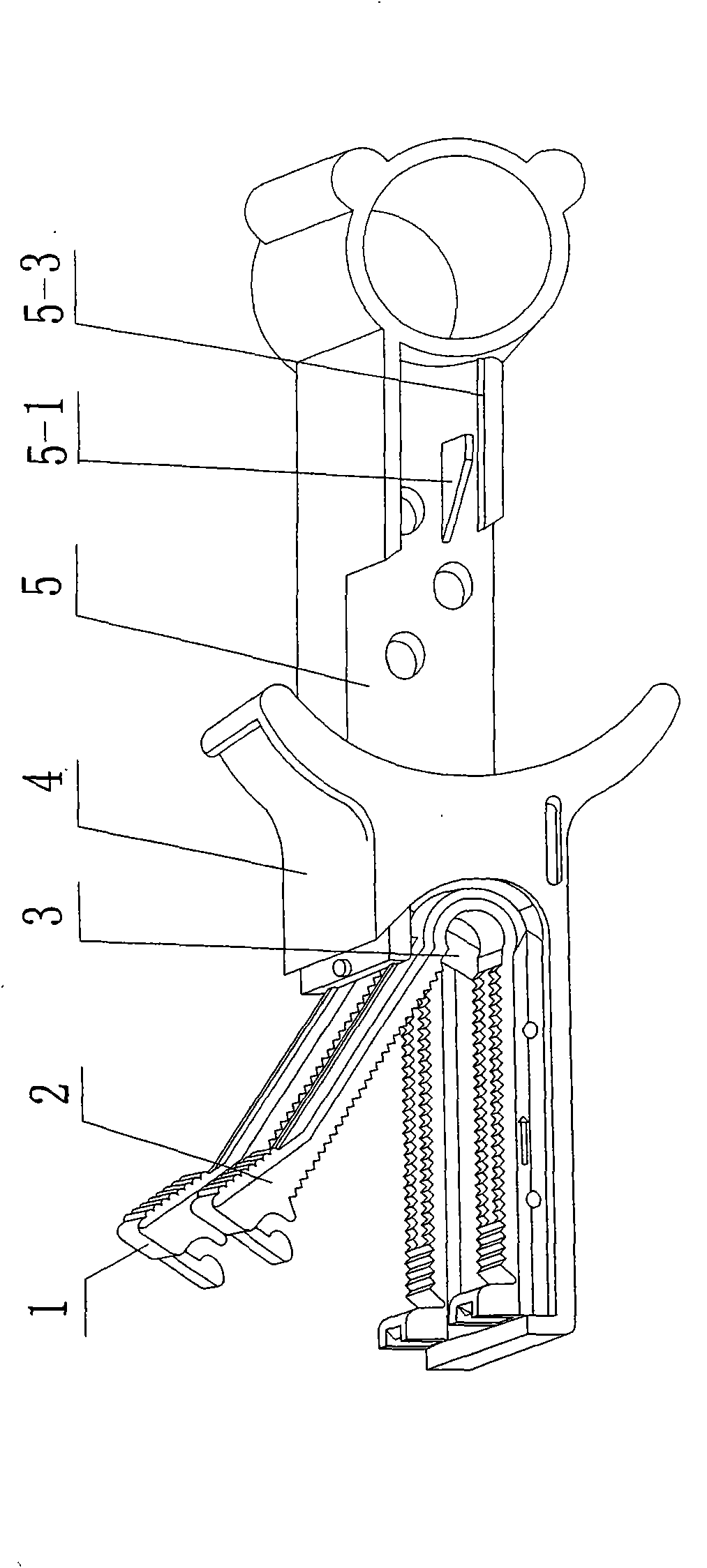
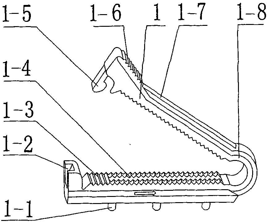
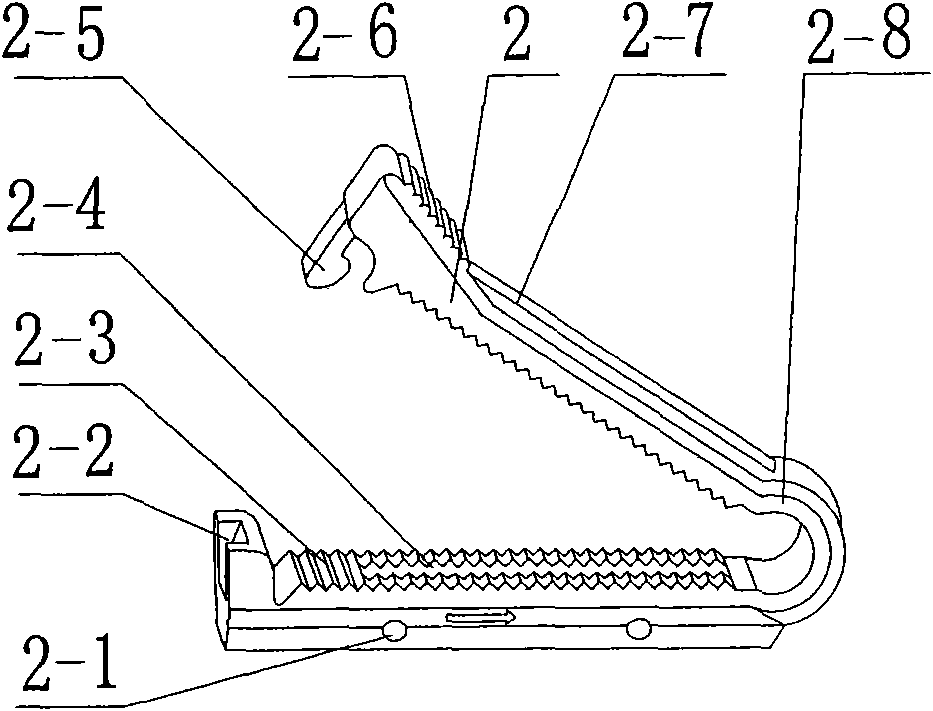
[0015] One end of the mother clamp 1 and the baby clamp 2 is a conjoined structure, and the conjoined bodies are circular 1-8, 2-8. There are ribs 1-7, 2-7 in the middle of the outer surface of the upper arm, and there are ribs 1-7 and 2-7 in the middle of the inner surface. The grooves 1-4, 2-4 position the umbilical cord, there are serrations 1-3, 2-3 around the groove, the open ends 1-6, 2-6 are tilted up for easy pressing, and there are hooks 1-5 on the inner wall , 2-5, with knurling on the outer surface, grooves 1-4, 2-4 on the inner surface of the lower arms of the female clamp 1 and baby clamp 2 corresponding to the inner surfaces of the upper arms of the female clamp and baby clamp And sawtooth 1-3, 2-3, there are rectangular buckle grooves 1-2, 2-2 matched with the hooks 1-5, 2-5 on the open end, there are through holes on the two sid...


PUM


Abstract

The invention provides an umbilic clamping cutter, comprising a pushing and cutting rod, a mother clamp, an infant clamp and a clamp holder, wherein one end of the pushing and cutting rod is provided with a blade while the other end is a cartoon; one surface of the pushing and cutting rod is fixed with a pick matched with the infant clamp; and one end of the clamp holder is connected with the mother clamp and the infant clamp while an inwall chute at the other end thereof is matched with the pushing and cutting rod. As one end of the clamp holder is manufactured into a big opening, only one end of the clamp holder operates by fingers, the whole operation process can be seen clearly from the big opening; the umbilical cord is clamped by two clamps in advance so as to facilitate the blade to cut; when in operation, the pushing and cutting rod is driven by hands to cut the umbilical cord actively like an injector, thus having easy cut-off and good cutting effect, saving labor, and avoiding blood from sputtering, thereby ensuring physical and psychological health of medical care personnel. The umbilical cord is clamped at first and then the blade is moved to cut, so the length of the reserved umbilical head can be short so as to shorten the drying time thereof, accelerate drop of umbilical head and avoid infection risk induced by the overlong reserved umbilical head.

Description

technical field [0001] The invention relates to a medical device, in particular to an umbilical cord clamping cutter which is used for cutting and connecting the umbilical cord between mothers and infants after birth, and can also clamp and seal the umbilical cord head at one time. Background technique [0002] Patent No. 98804728.4 "Clamping and Cutting Device", which consists of a holder with a blade and two clamps. The blade is installed on one end of the holder, and the two clamps slide in the chute embedded in the holder. In order to move the clamp from the hinged end of the two clamps to the other end, so that the two clamps are forced to close and clamp the clamped umbilical cord, and at the same time, the umbilical cord between the two clamps also encounters the blade on the clamp and is cut off At the same time, the first clamp is pushed out and clamped on the newborn by the clamper. This cutting device has a simple structure and has the functions of simultaneously ...

Claims


Application Information

Patent Timeline
Patent Type & Authority Applications(China)
IPC IPC(8): A61B17/125A61B17/42
Inventor 何定甫
Owner 宁波菲特医疗器械有限公司
Learn More